
Power transmission line sag measurement method based on infrared camera image processing

An infrared camera and image processing technology, applied in image data processing, measurement devices, image enhancement, etc., can solve the problems of short distance between obstacles, prone to short-circuit between phases, and large wire stress.

Inactive Publication Date: 2016-09-28
INST OF ADVANCED TECH UNIV OF SCI & TECH OF CHINA
View PDF11 Cites 10 Cited by
  • Summary
  • Abstract
  • Description
  • Claims
  • Application Information

AI Technical Summary

Problems solved by technology

If the sag is too small, the conductor stress will be too large, which will affect the mechanical safety of the conductor; if the sag is too large, the distance between the line and the ground and nearby obstacles will be too close, which will cause safety hazards to people and animals under the transmission line, and line galloping will easily occur Interphase short circuit
At present, the methods for on-line monitoring of transmission line sag mainly include temperature stress method and inclination angle method. These methods require many assumptions as the premise of the model, and the measurement results are either too conservative or very different from the actual situation, and have not reached the accuracy of sag measurement. actual purpose

Method used


Image

  • Power transmission line sag measurement method based on infrared camera image processing
  • Power transmission line sag measurement method based on infrared camera image processing
  • Power transmission line sag measurement method based on infrared camera image processing

Examples


Embodiment Construction

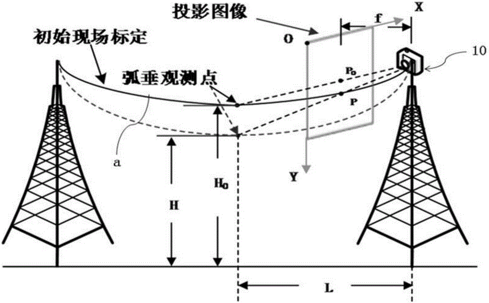
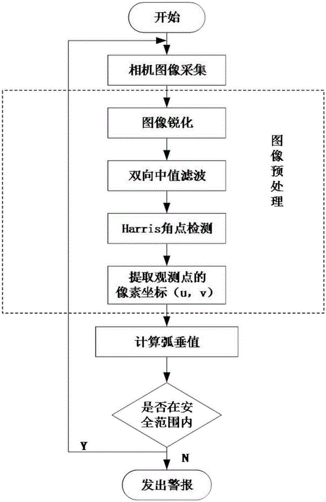
[0058] to combine Figure 1 to Figure 4 , the present invention is further described:

[0059] A transmission line sag measurement method based on infrared camera image processing, the measurement method includes the following steps:

[0060] Step A), the measurement site and the infrared camera 10 are calibrated;

[0061] Step B), obtain the image information near the sag observation point through the infrared camera, process the image, and extract the pixel coordinates P(u,v) of the observation point;

[0062] In step C), the processed image data obtained in step B is calculated to obtain the sag H of the transmission line;

[0063] Step D), judging whether the transmission line sag H is within the safe range, if the transmission line sag H is not within the safe range, the information is sent to the monitoring terminal 20, and the monitoring terminal 20 receives the information and outputs an alarm message; if the transmission line sag H Within safe limits, return to step ...


PUM


Abstract

The invention relates to a power transmission line sag measurement method based on infrared camera image processing. The method comprises the following steps of calibrating a measurement site and an infrared camera; through the infrared camera, acquiring image information near a sag observation point, processing an image and extracting a pixel coordinate of the observation point; acquiring processed image data and calculating so as to obtain a sag of a power transmission line; determining whether the sag of the power transmission line is in a safe range, if the sag of the power transmission line is not in the safe range, sending information to a monitoring terminal, receiving the information and then outputting alarm information by the monitoring terminal; and if the sag of the power transmission line is in the safe range, returning to the step that the infrared camera acquires the image information near the sag observation point. By using the method of the invention, a calculating model is concise and all-weather real-time on-line monitoring can be performed on the power transmission line sag. During establishing a system, less equipment is required, performance is reliable, the structure is simple and cost is low.

Description

technical field [0001] The invention relates to the technical field of on-line monitoring of electric power systems, and in particular relates to a transmission line sag measurement method based on infrared camera image processing. Background technique [0002] With the development of my country's economy, the demand for electric energy in industrial production and residents' daily life continues to grow, which puts forward higher requirements for the transmission capacity of my country's power grid. Raising the operating upper limit of the transmission network is a more economical and feasible solution to reduce the operating cost of the power grid and alleviate the transmission pressure. According to statistics, the operating upper limit of the existing transmission network has the potential to increase by 5% to 20%. [0003] Sag is the main restrictive factor for the upper limit of the transmission network operation. Line operating load, conductor temperature, stress, ice...

Claims


Application Information

Patent Timeline
IPC IPC(8): G06T7/00G01B11/03
CPCG01B11/03G06T2207/10048
Inventor 程健李军陈柱吴嘉珉史一明
Owner INST OF ADVANCED TECH UNIV OF SCI & TECH OF CHINA
Learn More