A scissor linkage type annular space deployable antenna mechanism
A circular space and linkage technology, applied in antennas, folded antennas, electrical components, etc., can solve the problems of complex structure, poor rigidity, and heavy weight of loop antennas, and achieve weight and material cost reduction, high structural rigidity, and high density small effect
- Summary
- Abstract
- Description
- Claims
- Application Information
AI Technical Summary
Problems solved by technology
Method used
Image
Examples
specific Embodiment approach 1
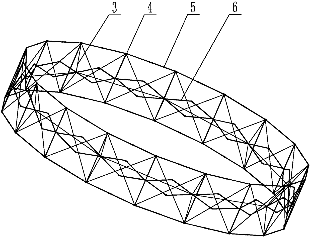
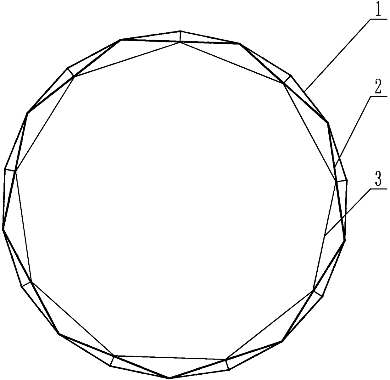
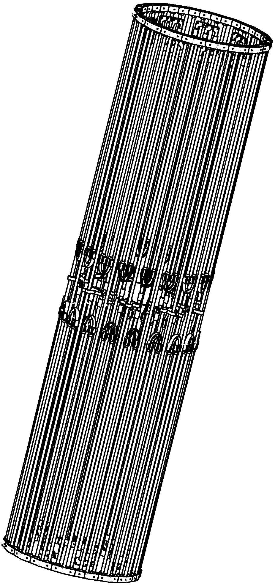
[0025] Specific implementation mode one: combine Figure 1 to Figure 12 To illustrate, a scissors-linked annular space expandable antenna mechanism described in this embodiment includes an outer ring 1, an inner ring 2 and a plurality of ropes 3, and ropes 3 are evenly arranged between the outer ring 1 and the inner ring 2, and the outer ring 1 includes a plurality of outer ring mechanisms connected end to end in sequence, each outer ring mechanism includes a vertical rod 4 and two side rods 5, the two side rods 5 are arranged in parallel, and a vertical rod 4 is arranged on two Between the side bars 5, between the side bars 5 and the vertical bars 4, between the vertical bars 4 and the vertical bars 4, and between the side bars 5 and the side bars 5 are all provided with ropes 3, and the inner ring 2 includes a plurality of inner ring mechanisms , a plurality of inner ring mechanisms are connected end to end in sequence, each inner ring mechanism includes scissors 6 and a ver...
specific Embodiment approach 2
[0030] Specific implementation mode two: combination Figure 1 to Figure 6 and Figure 10 to Figure 12 Note that the side bar 5 in this embodiment includes a side bar hinge 7, an elastic hinge 14 and two side links 13, the two side links 13 are connected by the elastic hinge 14, and the side bar hinge 7 is arranged on two adjacent outer bars. Between the ring mechanisms, one end of the side bar hinge 7 is rotatably connected to a side link 13 in an outer ring mechanism, and the other end of the side bar hinge 7 is rotatably connected to another side link 13 in the adjacent outer ring mechanism, The vertical rods 4 are respectively vertically affixed to the two side rod hinges 7 in the same outer ring mechanism. Other compositions and connection methods are the same as those in Embodiment 1.
[0031] When the side bar 5 is folded, the elastic hinge 14 bends to generate elastic force, so that the side link 13 has a tendency to extend and rotate outwards, providing power for th...
specific Embodiment approach 3
[0033] Specific implementation mode three: combination Figure 1 to Figure 9 Explain that the scissors 6 in this embodiment include a scissors hinge 8, two long connecting rods 10, two torsion springs 11 and four short connecting rods 9, and the middle parts of the two long connecting rods 10 cross through the scissors hinge 8 Set, the two ends of each long connecting rod 10 are respectively connected with a short connecting rod 9, between the long connecting rod 10 and the short connecting rod 9 are rotationally connected, the two ends of one of the long connecting rod 10 and the short connecting rod 9 A torsion spring 11 is provided, and the two short connecting rods 9 on one side are rotatably connected to the vertical bar hinges 12 respectively, and the short connecting rods 9 on the other side are respectively rotatably connected to the adjacent vertical bar hinges 12 . Other compositions and connection modes are the same as those in Embodiment 1 or 2.
[0034] The verti...
PUM
 Abstract
Description
Claims
Application Information
 - R&D
- Intellectual Property
- Life Sciences
- Materials
- Tech Scout
- Unparalleled Data Quality
- Higher Quality Content
- 60% Fewer Hallucinations
Browse by: Latest US Patents, China's latest patents, Technical Efficacy Thesaurus, Application Domain, Technology Topic, Popular Technical Reports.
© 2025 PatSnap. All rights reserved.Legal|Privacy policy|Modern Slavery Act Transparency Statement|Sitemap|About US| Contact US: help@patsnap.com


