A space-based retractable telescopic binary optical camera mechanism

A binary optics, sleeve-type technology, applied in optics, cameras, focusing devices of cameras, etc., can solve the problems of large mass, easy blocking of shooting light, difficulty in repeated expansion and contraction, etc., and achieves light weight and simple expansion movement. , the effect of easy installation and function expansion

Active Publication Date: 2017-08-25
HARBIN INST OF TECH
View PDF8 Cites 0 Cited by
  • Summary
  • Abstract
  • Description
  • Claims
  • Application Information

AI Technical Summary

Problems solved by technology

[0004] The purpose of the present invention is to provide a space-based retractable sleeve-type binary optical camera mechanism to solve the problems that the current space optical camera has a large mass, is difficult to repeatedly expand and contract, and is easy to block the shooting light.

Method used


Image

  • A space-based retractable telescopic binary optical camera mechanism
  • A space-based retractable telescopic binary optical camera mechanism
  • A space-based retractable telescopic binary optical camera mechanism

Examples


specific Embodiment approach 1

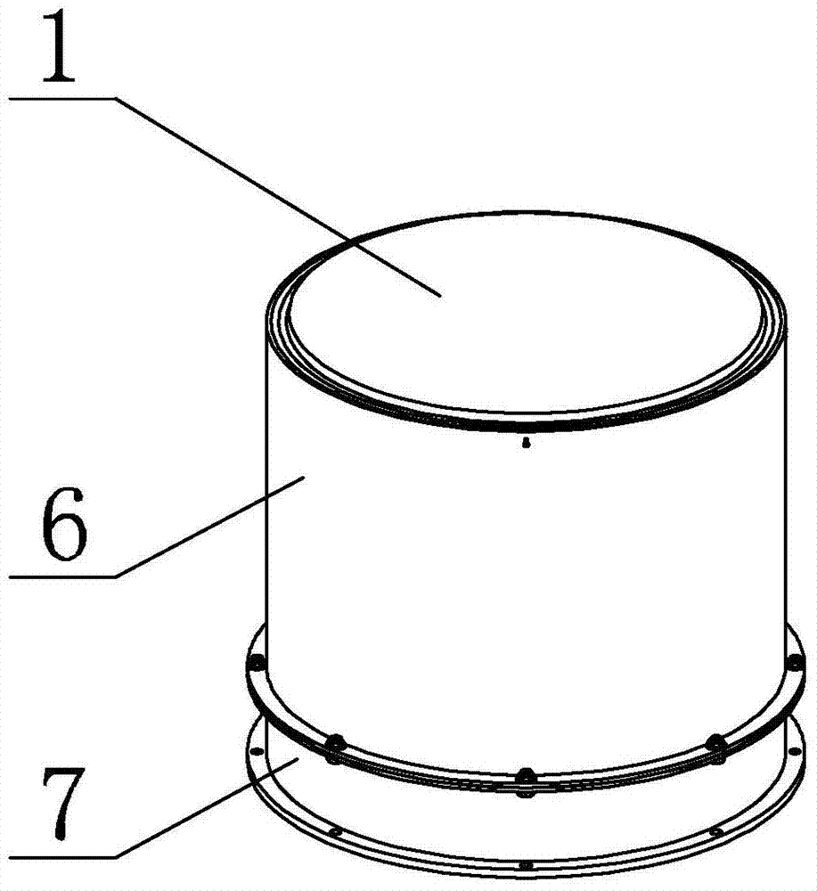
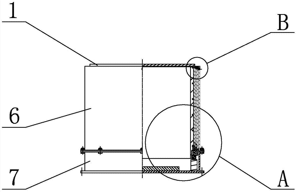
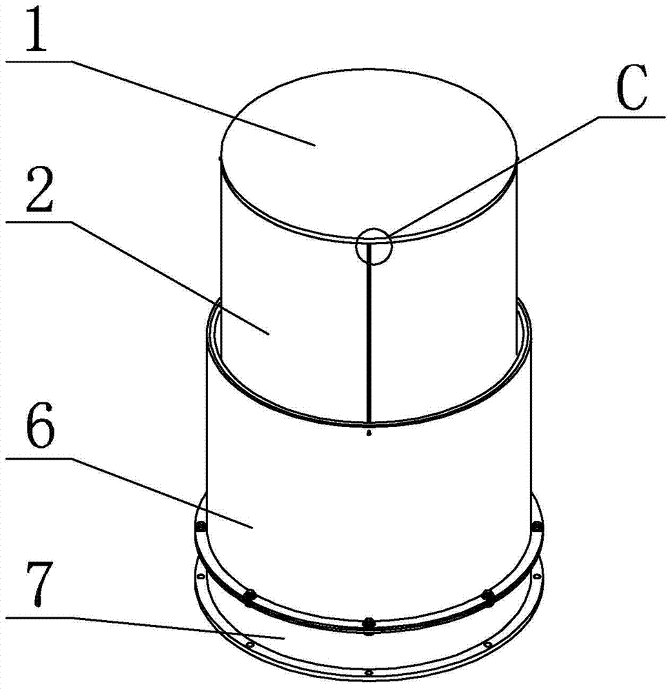
[0035] Specific implementation mode one: combine figure 1 , figure 2 , image 3 , Figure 4 , Figure 5 , Image 6 , Figure 7 , Figure 8 , Figure 9 , Figure 10 , Figure 11 , Figure 12 , Figure 13 , Figure 14 with Figure 15Describe this embodiment, in this embodiment it includes camera main mirror 1, first telescopic cylinder 2, second telescopic cylinder 4, at least one third telescopic cylinder 5, fixed cylinder 6, drive cylinder 8, base 7, bearing support system 9. Gear transmission mechanism 10, stepper motor 11, bottom receiving mirror 12 and locking mechanism 3, the first telescopic cylinder 2, the second telescopic cylinder 4, at least one third telescopic cylinder 5 and the fixed cylinder 6 from above From the bottom to the bottom, the camera lens barrel is formed by connecting with the locking mechanism 3. The outer diameter of the first telescopic tube 2 is smaller than the outer diameter of the second telescopic tube 4, and the outer diameter o...

specific Embodiment approach 2

[0040] Specific implementation mode two: combination figure 1 , figure 2 , image 3 , Figure 4 , Figure 5 , Image 6 , Figure 7 , Figure 8 , Figure 9 with Figure 16 Describe this embodiment, the first telescopic tube 2 in this embodiment includes a first tube body 2-1, a plurality of first guide wheels 2-2 and a plurality of first guide rails 2-4, the first tube body 2-1 A plurality of first guide wheels 2-2 are evenly distributed along the circumferential direction of the first cylinder body 2-1 on the inner wall of the bottom of the first cylinder body 2-1. A plurality of first taper pin holes 2-3 are evenly processed in the circumferential direction of the first barrel body 2-1, and a plurality of first taper pin holes 2-3 are evenly arranged on the outer wall of the first barrel body 2-1 along the axial direction of the first barrel body 2-1. Rails 2-4.

[0041] In this embodiment, multiple first guide rails 2-4 all move synchronously, and the optimal numb...

specific Embodiment approach 3

[0043] Specific implementation mode three: combination Figure 5 , Image 6 , Figure 7 , Figure 8 with Figure 10 Describe this embodiment. In this embodiment, the locking mechanism 3 includes multiple sets of first locking devices 3-1, and the second telescopic tube 4 includes a second tube body 4-1 and multiple second guide wheels 4. -2 and a plurality of second guide rails 4-4, the inner wall of the bottom of the second cylinder body 4-1 is evenly distributed with a plurality of second guide wheels 4-2 along the circumferential direction of the second cylinder body 4-1, so A plurality of second taper pin holes 4-3 are evenly processed on the outer wall of the bottom of the second cylinder body 4-1 along the circumferential direction of the second cylinder body 4-1, The axial direction of the second cylinder body 4-1 is evenly provided with a plurality of second guide rails 4-4, and the upper end of each second guide rail 4-4 is correspondingly provided with a set of f...


PUM


Abstract

The invention relates to a telescopic sleeve type camera mechanism and provides a space-based telescopic sleeve type binary optical camera mechanism to solve the problems that an existing space optical camera is large in weight and hard to stretch and retract repeatedly, and the photographing light path can be blocked easily in the using process. According to the space-based telescopic sleeve type binary optical camera mechanism, a first telescopic sleeve, a second telescopic sleeve, at least one third telescopic sleeve and a fixed sleeve are connected through a plurality of locking devices from top to bottom in sequence to form a camera lens cone; the outer diameter of the first telescopic sleeve is smaller than that of the second telescopic sleeve; the outer diameter of the second telescopic sleeve is smaller than that of the third telescopic sleeves; a main camera lens is arranged on the top of the first telescopic sleeve; a driving sleeve is sleeved with the fixed sleeve; the bottom of the fixed sleeve is provided with a base; a bottom-end receiving lens is arranged on the base and located at the center of the camera lens cone; a bearing supporting system is located between the driving sleeve and the fixed sleeve; a stepping motor is connected with the driving sleeve through a gear transmission mechanism. The space-based telescopic sleeve type binary optical camera mechanism is applied to the field of spaceflight optical remote sensing.

Description

technical field [0001] The invention specifically relates to a space expandable sleeve type binary optical camera mechanism. Background technique [0002] Binary optics is a new branch of optics developed based on the theory of light wave diffraction. It is a frontier discipline formed by the mutual penetration and intersection of optics and microelectronics technology. Binary optical devices, also known as diffractive optical devices, have the advantages of small size, light weight, easy replication, low cost, high diffraction efficiency, many degrees of design freedom, wide choice of materials, and unique dispersion properties. In many fields such as optical fiber communication, image processing, biomedicine, national defense and military affairs, it is showing an unprecedented important role and broad application prospects. Applying binary optics technology to aerospace optical remote sensing system helps to reduce the volume and weight of the system, reduce the cost of ...

Claims


Application Information

Patent Timeline
Patent Type & Authority Patents(China)
IPC IPC(8): G03B3/00
Inventor 刘荣强高明星郭宏伟邓宗全
Owner HARBIN INST OF TECH
Why Eureka
Try Eureka