Check patentability & draft patents in minutes with Patsnap Eureka AI!

Rotational angle detecting device

A technology of rotation angle detection and rotation angle, which is applied in measuring devices, electromechanical devices, special recording/indicating devices, etc., can solve the problems of time-consuming and labor-intensive data

Active Publication Date: 2016-09-28
DENSO CORP
View PDF6 Cites 2 Cited by
  • Summary
  • Abstract
  • Description
  • Claims
  • Application Information

AI Technical Summary

Problems solved by technology

Also, take the time and effort to prepare the data

Method used


Image

  • Rotational angle detecting device
  • Rotational angle detecting device
  • Rotational angle detecting device

Examples


no. 1 example

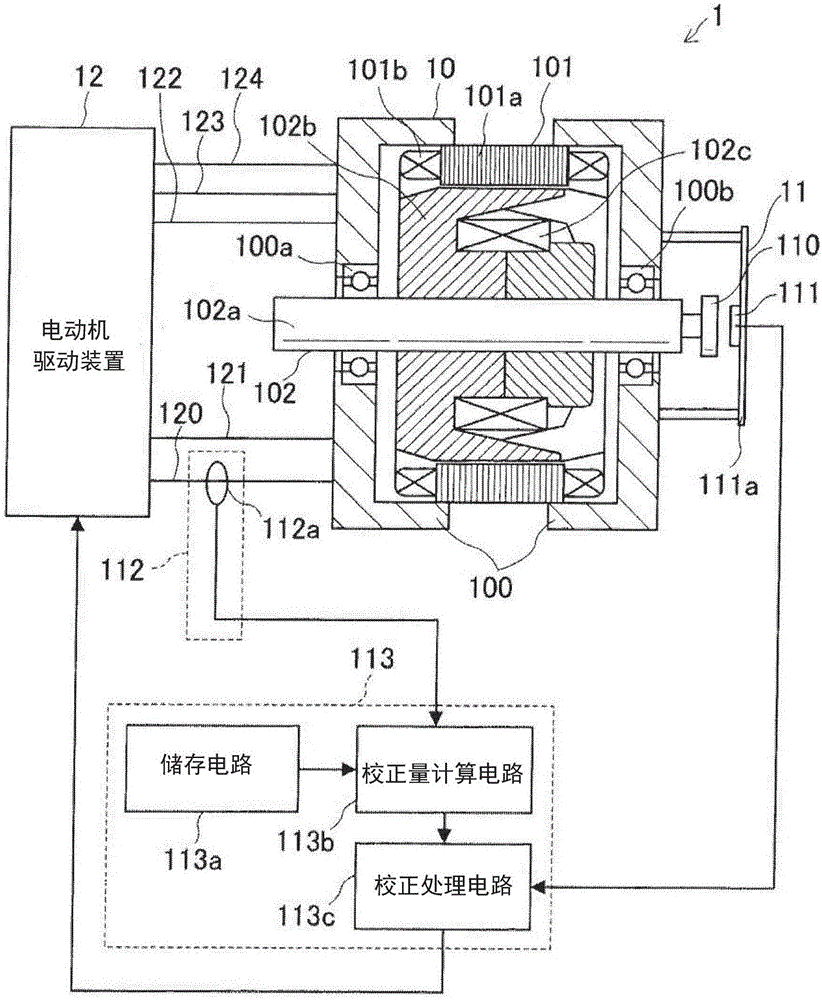
[0036] First, refer to figure 1 and figure 2 The configuration of the motor in the first embodiment is described.

[0037] figure 1 The motor drive system 1 shown in is a system that generates torque by driving a motor.

[0038] The motor drive system 1 includes a motor 10 , a rotation angle detection device 11 and a motor drive device 12 .

[0039] The electric motor 10 is a device that generates torque by an electric current flowing through the electric motor 10 . The motor 10 includes a housing 100 , a stator 101 and a rotor 102 .

[0040] The housing 100 accommodates the stator 101 and the rotor 102 and is also a part that rotatably supports the rotor 102 . The housing 100 is provided with bearings 100a, 100b.

[0041] The stator 101 is a part that constitutes a part of a magnetic circuit and generates magnetic flux and forms a rotating magnetic field by being supplied with three-phase alternating current.

[0042] The stator 101 includes a stator core 101a and a s...

no. 2 example

[0152] Next, a motor drive system of the second embodiment will be described.

[0153] Compared to the motor drive system of the first embodiment in which the relationship between the disturbance magnetic flux and the rotation angle error is expressed by a single linear expression, the motor drive system of the second embodiment corresponds to this relationship by two defined for each region Situations represented by linear expressions.

[0154] First, the configuration of a motor drive system according to the second embodiment will be described.

[0155] The configuration of this motor drive system is the same as that of the first embodiment except for the operation of the correction circuit.

[0156] Therefore, will refer to Figure 5 together with reference figure 1 The circuit of the motor drive system in the first embodiment Figure 1 The configuration of the correction circuit in the motor drive system of the second embodiment will now be described.

[0157] figure...


PUM


Abstract

The invention discloses a rotational angle detecting device. A correction circuit 113 stores data for obtaining coefficients of a relational expression indicating a relationship between a disturbance magnetic flux and a rotational angle error. Then, the coefficients are obtained from the data for obtaining the coefficients, and a detection result of a magnetic sensor 111 is corrected based on the coefficients obtained, a relational expression, and a detection result of a disturbance magnetic flux detection circuit 112. Since it is possible to obtain the rotational angle error with respect to the disturbance magnetic flux from the coefficient obtained and the relational expression, it is not necessary to store the data indicating the relationship between the disturbance magnetic flux and the rotational angle error for all of the disturbance magnetic flux value in disturbance magnetic flux regions that may be applied.

Description

technical field [0001] The invention relates to a rotation angle detection device, which is provided with a correction circuit for correcting the detection result. Background technique [0002] Conventionally, Japanese Patent No. 4783752 discloses a resolver, for example, as a rotation angle detection device provided with a correction circuit for correcting detection results. [0003] This resolver includes a PROM, a correction coefficient calculation unit, and a correction unit. [0004] Here, the PROM, the correction coefficient calculation section, and the correction section correspond to a correction circuit. [0005] The resolver is a device that detects the rotation angle of the rotation shaft of the motor. [0006] The resolver is mounted on the rotating shaft of the motor. [0007] At the same time, when current flows through the motor, there is magnetic flux leaking from the rotating shaft. [0008] Therefore, the leaked magnetic flux is applied to the resolver ...

Claims


Application Information

Patent Timeline
Patent Type & Authority Applications(China)
IPC IPC(8): H02K11/20
CPCG01D3/0365G01D5/24485G01D5/145
Inventor 川村卓也金城博文胁本亨中山英明吉村雅贵
Owner DENSO CORP
Features
  • R&D
  • Intellectual Property
  • Life Sciences
  • Materials
  • Tech Scout
  • Unparalleled Data Quality
  • Higher Quality Content
  • 60% Fewer Hallucinations
Learn More