Virtual positioning plate and building detection method with application of virtual positioning plate

A detection method and positioning plate technology, applied in the field of virtual positioning plates, can solve the secondary damage of buildings, damage to the supporting force, force balance, load, shear force, camber, and can not be left on the ground or object surface by external force means. Record the traces and save the first reference point, so as to achieve the effect of convenient portability and easy operation and implementation.

Inactive Publication Date: 2016-10-05
LEADERTEK
View PDF5 Cites 2 Cited by
  • Summary
  • Abstract
  • Description
  • Claims
  • Application Information

AI Technical Summary

Problems solved by technology

[0004] The second difficulty in establishing the datum point is that the feature cannot damage the building itself or its surroundings. In other words, the feature cannot be "fixed" on the datum point by means of external force (such as nailing, locking...); It belongs to monuments, ruins, archaeological sites, etc., and fixing the features to the reference point by external force will inevitably cause secondary damage to the building; in addition, the structure of some buildings (such as bridges, piers, tunnels...) is extremely Precise, if an external force is used to set a feature at the reference point, it may damage the supporting force, force balance, load, shear force, camber, etc. of the building
[0005] The third difficulty in setting up benchmark points is that if building monitoring needs to perform the first, second, third, etc. 3D laser scanning and point cloud data establishment at different times (such as bridge crack monitoring...), each time The reference points must be the same, so that the variables of the building can be calculated through software reconstruction; however, if the features cannot be fixed by external force means, or the record marks cannot be left on the ground or object surface by external force means, the first reference point If the points are saved, how to reproduce the benchmark points set up for the first time in the second and third scans?

Method used


Image

  • Virtual positioning plate and building detection method with application of virtual positioning plate
  • Virtual positioning plate and building detection method with application of virtual positioning plate
  • Virtual positioning plate and building detection method with application of virtual positioning plate

Examples


Embodiment Construction

[0039] In order to illustrate the central idea of ​​the present invention expressed in the column of the above-mentioned summary of the invention, it is expressed in specific embodiments. Various objects in the embodiments are drawn according to proportions, sizes, deformations or displacements suitable for illustration, rather than drawn according to the proportions of actual components, which are described first.

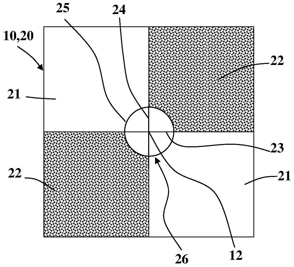
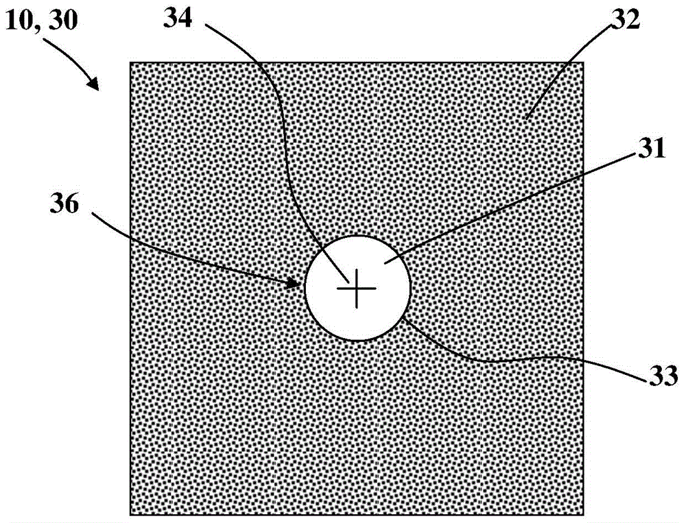
[0040] like figure 1 , figure 2As shown, the virtual positioning plate 10 provided by the present invention is a plate with a geometric shape and a predetermined thickness. The virtual positioning plate 10 has a first surface 20 and a second surface 30 that are different. The material of the virtual positioning board 10 includes but not limited to plastic, metal or composite material. The thickness of the virtual positioning board 10 includes but is not limited to 1mm˜4mm. The contour shape of the virtual positioning board 10 can be rectangular, circular, or v...


PUM


Abstract

The invention discloses a virtual positioning plate which comprises a plate body with a geometric shape and a predetermined thickness. The virtual positioning plate has a first surface and a second surface which is different from the first surface. The first surface has a first calibration, and the second surface has a second calibration. The virtual positioning plate is arranged in a 3D laser scanning system and is arranged at the reference point of a building or the periphery of the building. Each measuring station scans the building and the virtual positioning plate of the reference point so as to obtain the point cloud data about the building and the virtual positioning plate of the reference point of each measuring station. Software receives and calculates the point cloud data about the building and the virtual positioning plate of the reference point, interprets the 3D coordinate of each point cloud, and taking the center position coordinate of the virtual positioning plate as the characteristic point which overlaps the building point cloud data of each measuring station so as to form the three-dimensional point cloud image and data of the building.

Description

technical field [0001] The invention is a virtual positioning board arranged on a building or its peripheral reference points in a three-dimensional laser scanning system. Background technique [0002] The digital three-dimensional imaging of objects can be accomplished with a three-dimensional laser scanning system. The 3D laser scanner obtains the point cloud data of each surface of the object, and the back-end software constructs the point cloud data into a digital stereoscopic image of the object. Depending on the properties of the object, different 3D laser scanners and software are selected. The digital stereoscopic imaging of large-scale spatial objects such as buildings (architectures, monuments, ruins, and archaeological sites) needs to be achieved by using the ground-borne LiDAR (LiDAR) in the 3D laser scanning system. Due to the limitations of ground-borne lidar itself and the influence of large and complex building entities, some building entities are obscured ...

Claims


Application Information

Patent Timeline
Patent Type & Authority Applications(China)
IPC IPC(8): G01B11/00
Inventor 贾志强姚良居黄国轩叶羿伶林明洁
Owner LEADERTEK
Why Eureka
Try Eureka