Axial gap type rotation motor

A rotating electrical machine, axial gap technology, applied in synchronous motors with stationary armatures and rotating magnets, synchronous motors for single-phase current, electrical components, etc. , problems such as the reduction of the magnetic force of the permanent magnet

Active Publication Date: 2016-10-05
SUZUKI MOTOR CORP
View PDF16 Cites 7 Cited by
  • Summary
  • Abstract
  • Description
  • Claims
  • Application Information

AI Technical Summary

Problems solved by technology

[0004] However, in the permanent magnet, when the high-order space harmonic flux interlinks, it will generate heat due to the eddy current generated inside, the coercive force will decrease, and the magnetic force will become irreversibly smaller
Therefore, as described in Patent Document 1, for example, in a rotating electrical machine of the type in which permanent magnets are embedded on the rotor side where high-order spatial harmonic magnetic fluxes are interlinked, the magnetic force of the permanent magnets is reduced, and good driving cannot be achieved. question
[0005] In order to solve this problem, an expensive magnet with a high coercive force added with a large amount of heavy rare earths such as dysprosium (Dy) and terbium (Tb) was conceived, but the cost will increase
[0006] In addition, as described in Patent Document 2, in order to wind the strip-shaped wire around the core material, it is necessary to draw out the connection ends of the winding from the inner and outer sides of the winding coil, and if the core material is cut to secure a space for drawing out etc., the area through which the magnetic flux passes will become smaller, which will lead to a reduction in the driving efficiency of the rotating machine
In addition, when the strip-shaped wire is drawn out from the edge of the end surface of the core, a gap will be formed with the members located above and below the core, which hinders miniaturization.

Method used


Image

  • Axial gap type rotation motor
  • Axial gap type rotation motor
  • Axial gap type rotation motor

Examples


Embodiment Construction

[0094] Hereinafter, embodiments of the present invention will be described in detail with reference to the drawings. Figure 1 to Figure 27 It is a figure explaining the axial gap type electric rotating machine which is one embodiment of this invention.

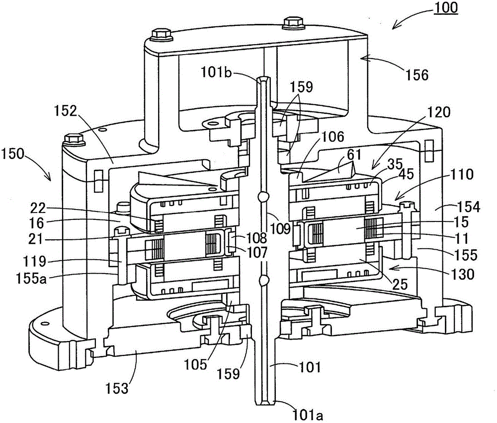
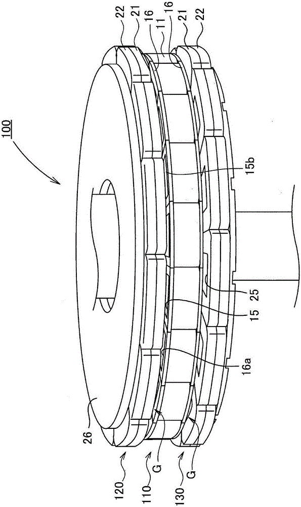
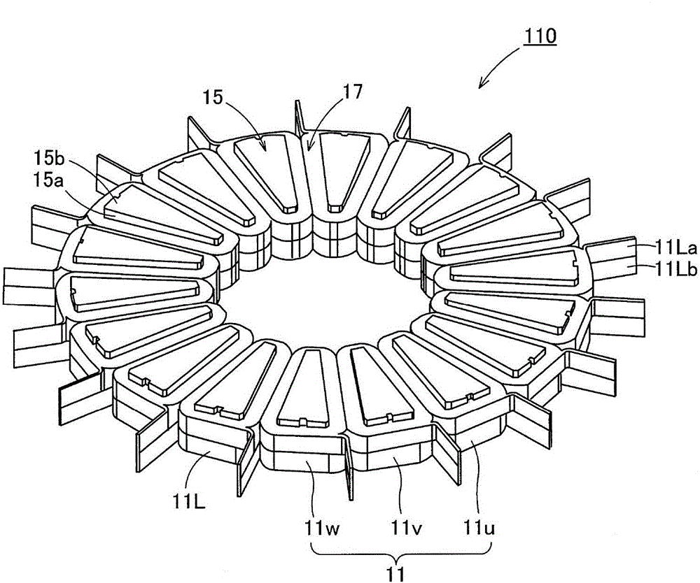
[0095] exist figure 1 and figure 2 Among them, the rotating electric machine 100 is provided with a stator 110 and two rotors 120 and 130 formed in a substantially disk shape, and as described later, there is no need to input energy to the rotors 120 and 130 from the outside by means of contact using slip rings or the like. The structure, for example, has performance suitable for being mounted on a hybrid vehicle or an electric vehicle.

[0096] In this rotating electric machine 100, two rotors 120, 130 are attached to a shaft (rotary shaft) 101 penetrating the shaft center, respectively, and are sandwiched by opposite sides of a stator 110 with a gap G therebetween. The stator 110 supports the shaft 101 so that It can r...


PUM


Abstract

The invention discloses an axial gap rotation motor of a big electromagnetic torque winding excitation structure axial gap type rotary motor which is obtained through high order spatial harmonic flux generated by an armature coil. The axial gap rotation motor (100) has: two rotord (120,130) which performs rotation driving with an axis (101) as a center and a stator (110), the two sides of which in an axial direction are opposite to the rotors; the axial gap rotation motor (100) comprises a plurality of armature coils (11) which are configured at the circumference of the axis of the stator, multiple induction coils (21) and multiple excitation coils (22) which are arranged on the circumference of the two rotors, and a diode which perform rectification on the induction current generated by the induction coils in order to provide the excitation coil; the windings of the armature coils, the induction coils and the excitation coil are winding coils which are wound into an alpha coil on an iron core (15,25) in an axial direction.

Description

technical field [0001] The present invention relates to an axial gap type rotating electrical machine utilizing winding excitation. Background technique [0002] In a rotating electrical machine, the rotor and the stator face each other across a gap. For example, the magnetic flux generated by the armature coil arranged on the stator side is interlinked on the rotor side to form a magnetic circuit, thereby obtaining a rotational force (reluctance torque). In order to assist this rotational force, permanent magnets and field windings (electromagnets) may be arranged to utilize electromagnetic torque. [0003] In such a rotating electrical machine, an axial type in which the stator and the rotor face each other in the axial direction has been proposed (Patent Document 1), and it has also been proposed to wind a strip-shaped wire as a winding around a core material on the stator side. A technical solution to form an armature coil (Patent Document 2). [0004] However, in the ...

Claims


Application Information

Patent Timeline
Patent Type & Authority Applications(China)
IPC IPC(8): H02K16/02H02K21/24
CPCH02K16/02H02K21/24H02K3/522H02K11/042H02K19/12H02K2203/09
Inventor 中岛一清邓家宁青山真大
Owner SUZUKI MOTOR CORP
Why Eureka
Try Eureka