Suctioning device for large artificial water bodies

A technology for suction equipment and water bodies, which is applied in the field of suction equipment and can solve problems such as inability to use large-scale applications, damage to coatings, and disabling of large-scale artificial water bodies.

Active Publication Date: 2016-10-05
CRYSTAL LAGOONS CURACAO
View PDF18 Cites 0 Cited by
  • Summary
  • Abstract
  • Description
  • Claims
  • Application Information

AI Technical Summary

Problems solved by technology

Because the system is actuated by hand within the perimeter, it cannot be used for large applications or for cleaning large surface areas for short periods of time
Furthermore, the rotatable sphere does not allow the treatment of protrusions or irregularities in the bottom of large artificial water bodies since the rotatable sphere may damage the coating of these large artificial water bodies.
[0022] It must therefore be noted that none of the suction cleaners used to operate in swimming pools according to technique A will be useful or effective for suctioning the bottom of large artificial bodies of water using technique B
[0023] However, several specialized suction devices have been developed for use in large artificial water bodies according to Technology B, wherein these suction devices have the same speed, reversibility, turning ability, suction efficiency, Various limitations related to operation in regular surfaces and operation in sloping bottoms

Method used


Image

  • Suctioning device for large artificial water bodies
  • Suctioning device for large artificial water bodies
  • Suctioning device for large artificial water bodies

Examples


example 1

[0088] A suction device according to the present invention was fabricated and installed in a 3.7 acre large body of water.

[0089] The water body includes an LLDPE (Linear Low Density Polyethylene) liner which is installed on sandy soil creating an irregular bottom which must be thoroughly cleaned to maintain proper water color and tone. Other technologies cannot clean such large bodies of water, and therefore the suction device according to the invention was developed and tested at the site.

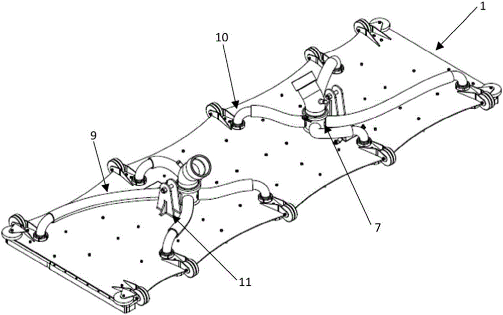
[0090] The suction device consisted of a flexible sheet constructed of polycarbonate with a thickness of 10 mm to provide the required flexibility. The suction device has approximately 3m 2 surface area and has general dimensions of 3 meters long and 1 meter wide. The height of the suction device is about 6 cm, which only allows suction of the bottom stream containing impurities and debris, but not clean water which would render the treatment inefficient.

[0091] The brushes are m...

example 2

[0103] A suction device according to the present invention was fabricated and installed at a large body of water of 20 acres. Large bodies of water have bottoms covered with LLDPE liners installed on sandy soils creating an irregular bottom that must be thoroughly cleaned to maintain proper water color and tone in the large body of water. Due to the recreational nature of the project, cleaning operations are carried out at night, and therefore the suction equipment and propulsion means include specific facilities (such as additional lights) and systems (such as GPS) to achieve this.

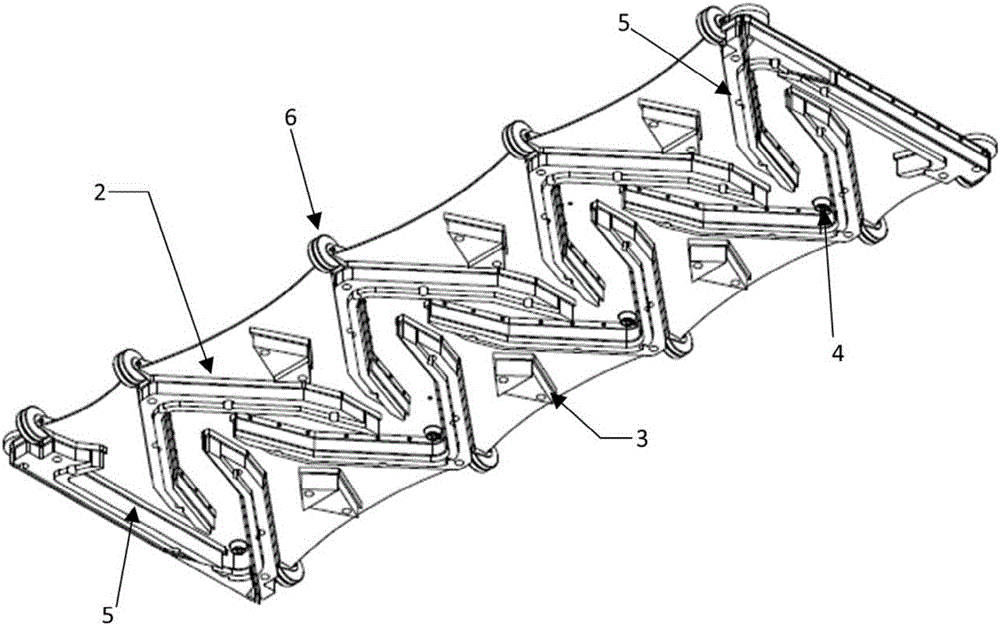
[0104] The suction device has a flexible sheet constructed of 316 steel with a thickness of 5mm to provide the flexibility required and the weight required to keep the device underwater and avoid while rising from the bottom. By providing steel sheets, the weight is distributed along the entire unit, thus increasing the stability of the unit. The surface of the suction device is approx. 3m 2 ,...


PUM

PropertyMeasurementUnit
surfaceaaaaaaaaaa
areaaaaaaaaaaa
thicknessaaaaaaaaaa

Abstract

The present invention discloses a suctioning device for suctioning flocculate generated by the flocculation or cohesion from the bottom of large artificial water bodies without centralized filtration system. The suctioning device comprises a flexible sheet, multiple brushes, a suction point, a safe wheel, a collector, an interior suction line, and a connection device used for framework. The water flow accessing the bottom of the suctioning device is equal to or higher than the water flow suctioned by the external pumping system.

Description

technical field [0001] The present invention relates to a suction device for suctioning flocs from the soft bottom of large artificial water bodies, where the bottom surface of large artificial water bodies may be irregular and inclined. U.S. Patent No.8,518,269, No.8,062,514, No.8,070,942, No.7,820,055, No.8,454,838, No.8,465,651, No.8,518,269, No.8,070,342 and U.S. Patent Application Publication No.20110110036, No.204910108 The entire contents of No.20130264261, No.20130213866, No.20130306532 and No.20110210076 are incorporated herein by reference. Background technique [0002] In the world today, one can identify two different techniques for maintaining water bodies. [0003] On the one hand, one can identify a traditional swimming pool water treatment technology, which will be referred to as "Technology A". On the other hand, one can identify an innovative water treatment technology for treating and maintaining large man-made water bodies, such as large man-made water ...

Claims


Application Information

Patent Timeline
Patent Type & Authority Applications(China)
IPC IPC(8): A47L9/06
CPCE04H4/1636E04H4/1672E04H4/1654E04H4/1645A46B9/10A46B13/02A47L9/0405B01D35/02B08B1/002B08B5/04B08B7/04B08B9/0856C02F1/52E02B3/02E04H4/16E02F3/885E02F3/8866E02F3/9243E02F3/9293E02F5/28E02F9/261
Inventor F·B·菲施曼托雷斯J·E·普里托多明戈斯
Owner CRYSTAL LAGOONS CURACAO
Why Eureka
Try Eureka