

Swivel chair base capable of leaning forward in adjustable mode
An adjustable and swivel chair technology, applied to vertically adjustable chairs, chairs, other seating furniture, etc., can solve problems such as inability to lift consumers, average effect, and single function
- Summary
- Abstract
- Description
- Claims
- Application Information
AI Technical Summary
Problems solved by technology
Method used
Image

Examples
Embodiment 1
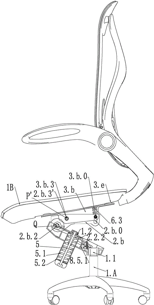
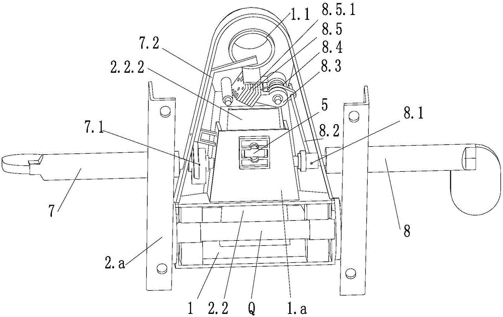
[0066] Such as Figure 1-8 As shown, the base plate 1 of the adjustable forward-tilting swivel chair base is a one-piece cast iron stamping and forming, and the whole is horizontally arranged. A lifting wrench 7 and an adjustable tilt wrench 8 are respectively arranged on both sides of the chassis base 1 .
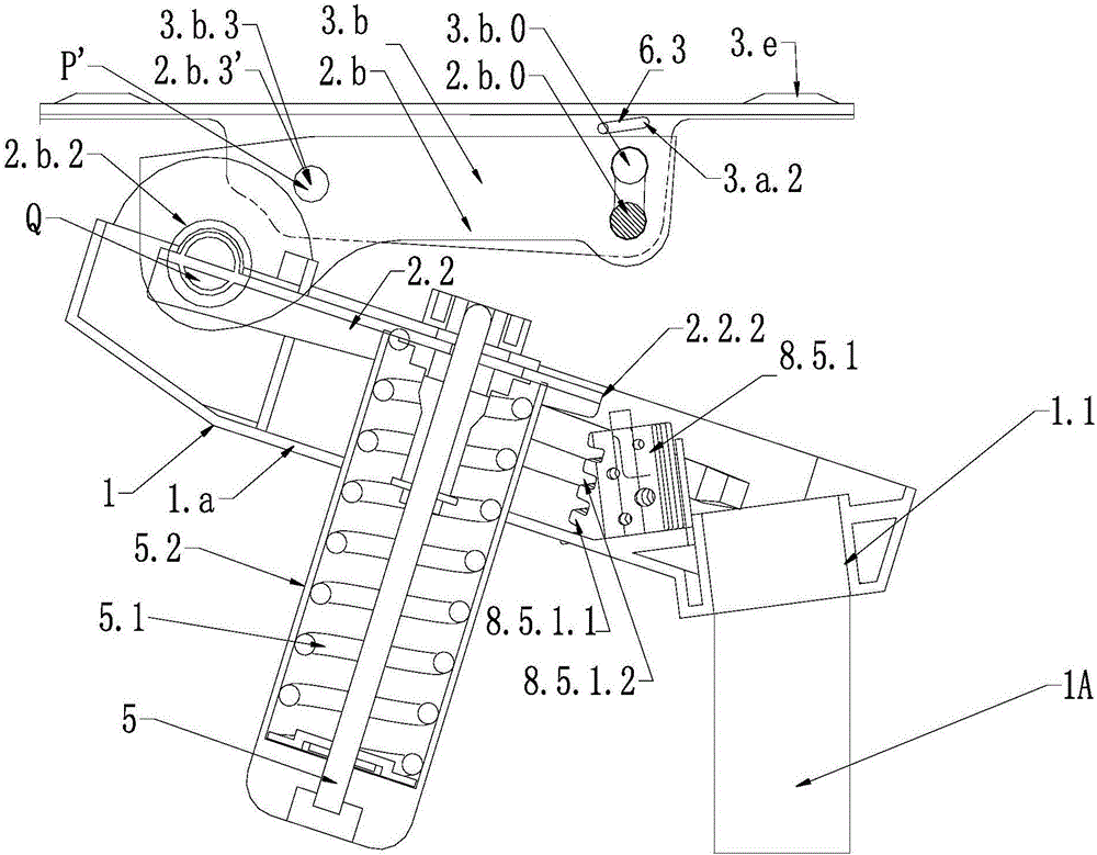
[0067] The middle plate 2 is installed above the chassis base 1 through the tilting axis Q; the tilting axis Q hinges the middle plate vertical wall 2. The forward tilting plate 3 is fitted on the top of the middle plate 2 through the forward tilting middle axis P'. The forward tilting pivot axis P' is hinged to the forward tilting plate vertical wall 3.b of the forward tilting plate 3 and the middle plate vertical wall 2.b of the middle plate 2.
[0068] The front end of the chassis base 1 is horizontally fitted with a tilting shaft Q. The middle part of the chassis seat 1 is the base middle plate 1.a. Open the tilting axis hole 1.a.1 of the base plate on the middle p...
Embodiment 2
[0087] Such as Figure 9-22 As shown, the base plate 1 of the adjustable forward-tilting swivel chair base is a one-piece cast iron stamping and forming, and the whole is arranged horizontally. The main body is the middle base plate 1.a, and the two sides of the base plate 1. A base plate vertical wall 1.b.
[0088] The middle plate 2 is installed above the chassis base 1 through the tilting axis Q; the tilting axis Q hinges the middle plate vertical wall 2. The forward tilting plate 3 is installed above the middle plate 2 through the forward tilting bottom rotating shaft P. The forward tilting bottom rotating shaft P is hinged to the forward tilting plate vertical wall 3.b of the forward tilting plate 3 and the base plate vertical wall 1.b of the chassis base 1 .
[0089] Each base plate vertical wall 1.b is sequentially provided with a base plate tilt pin hole 1.b.1, a base plate rotation axis hole 1.b.2, and a base plate forward tilt axis hole 1.b.3 from back to front. A...
Embodiment 3
[0108] This example Figure 23 Shown, substantially identical with embodiment 2, difference is:
[0109] The forward tilting plate 3 is fitted on the top of the middle plate 2 through the forward tilting middle axis P'. The forward tilting pivot axis P' is hinged to the forward tilting plate vertical wall 3.b of the forward tilting plate 3 and the middle plate vertical wall 2.b of the middle plate 2.
[0110] The middle plate 2 is provided with a middle plate forward tilting intermediate shaft hole 2.6.3', which is used to install the forward tilting intermediate shaft P'. The forward tilting axis P' passes through the forward tilting axis hole 1.b.3' of the base plate vertical wall 1.b of the base plate 1, and hinges the forward tilting plate 3 and the middle plate 2 so that the forward tilting plate 3 can move forward Tilting the axis of rotation P' is the axis of rotation.
[0111] The design of other places remains unchanged, adjust the distance between the large holes ...
PUM
| Property | Measurement | Unit |
|---|---|---|
| Edge thickness | aaaaa | aaaaa |
Abstract
Description
Claims
Application Information