Motor-end-cover tin soldering machine

A soldering machine and motor technology, applied in welding equipment, auxiliary devices, metal processing, etc., can solve the problems of unfavorable mass production operations, low processing efficiency of soldering machines, etc., achieve good performance, convenient operation, and improve processing efficiency Effect

Inactive Publication Date: 2016-10-12
QUANNAN CHAOYA TECH
View PDF12 Cites 7 Cited by
  • Summary
  • Abstract
  • Description
  • Claims
  • Application Information

AI Technical Summary

Problems solved by technology

[0002] The existing motor end cover soldering machine can only perform the soldering operation of one end cover, and the operation of each mechanism is completed manually. The processing efficiency of the soldering machine with this structure is very low, which is not conducive to mass production operations

Method used


Image

  • Motor-end-cover tin soldering machine
  • Motor-end-cover tin soldering machine
  • Motor-end-cover tin soldering machine

Examples


Embodiment Construction

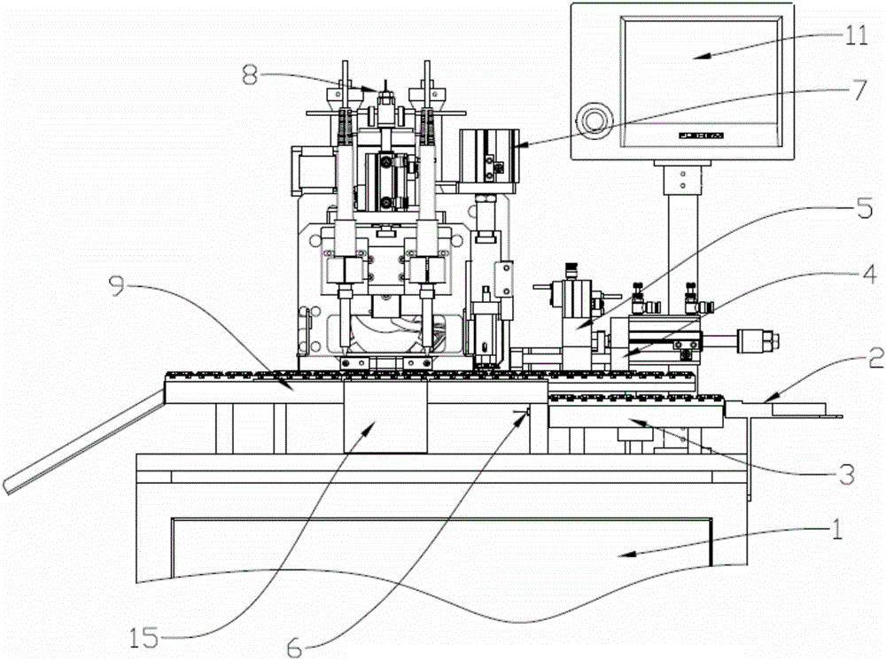
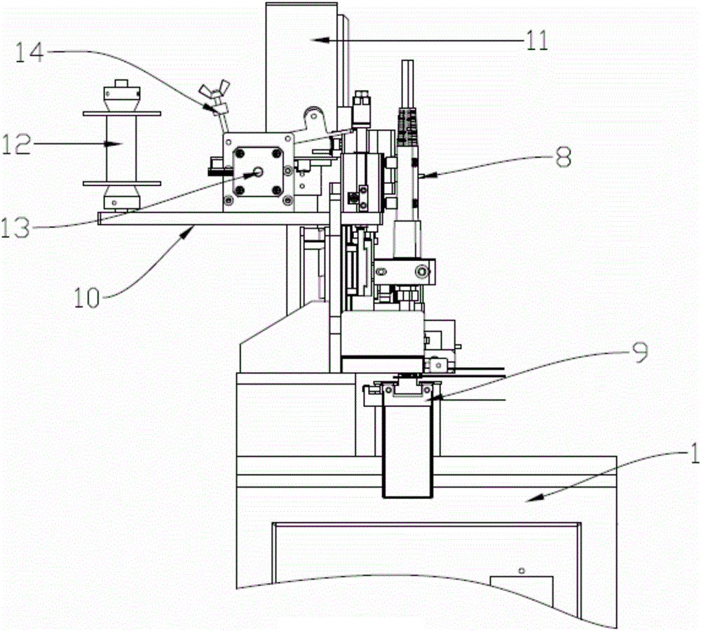
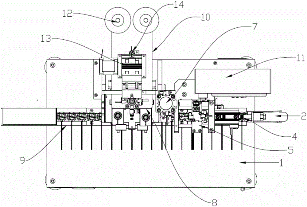
[0016] Through the following examples, combined with the attached Figure 1-3 , the technical solution of the present invention will be further specifically described.

[0017] A motor end cap soldering machine, comprising a machine body 1 and a feed track 2 arranged on the machine body 1, a feeding upper mechanism 3, a feeding pushing mechanism 4, a feeding pressing mechanism 5, a material sensor 6, a brush pressing mechanism 7, Welding mechanism 8, welding top mechanism 15, discharge track 9, tin feeding mechanism 10 and PLC controller 11 for controlling each mechanism; wherein the feeding top mechanism 3 and the feeding pressing mechanism 5 can reciprocate up and down, and the feeding The push mechanism 4 can reciprocate left and right, the feed track 2 is located below the right side of the discharge track 9, and is arranged in parallel up and down between the two, the feeding top mechanism 3 is located on the left side of the feed track 2, and The two are attached to eac...


PUM


Abstract

The invention relates to a motor-end-cover tin soldering machine. The motor-end-cover tin soldering machine comprises a machine body, feeding rails, a feeding mechanism, a feeding pushing mechanism, a feeding pressing mechanism, a material sensor, a brush pressing mechanism, a soldering mechanism, a soldering jacking mechanism, discharging rails, a tin feeding mechanism and an PLC for controlling the mechanisms, wherein the feeding rails, the feeding mechanism, the feeding pushing mechanism, the feeding pressing mechanism, the material sensor, the brush pressing mechanism, the soldering mechanism, the soldering jacking mechanism, the discharging rails, the tin feeding mechanism and the PLC are arranged on the machine body. The feeding rails are located below the right side of the discharging rails, the feeding mechanism is located on the left side of the feeding rails, the feeding pushing mechanism and the feeding pressing mechanism are arranged over the feeding mechanism, the brush pressing mechanism and the soldering mechanism are arranged over the discharging rails, the soldering jacking mechanism is arranged at the bottom of the discharging rail located under the soldering mechanism, and the PLC is arranged at the portion, behind the feeding rails, of the machine body. According to the motor-end-cover tin soldering machine, the flow-type structural design is adopted, processes of tin welding and the like of end covers are automatically completed through the machine, machining efficiency is effectively improved, and the motor-end-cover tin soldering machine is quite suitable for batch production.

Description

technical field [0001] The invention relates to the technical field of motor processing equipment, in particular to a motor end cover soldering machine. Background technique [0002] The existing motor end cover soldering machine can only perform the soldering operation of one end cover, and the operation of each mechanism is completed manually. The processing efficiency of the soldering machine with this structure is very low, which is not conducive to mass production. So we need a high-efficiency assembly line motor end cover soldering machine. Contents of the invention [0003] The object of the present invention is to provide a motor end cover soldering machine with high processing efficiency and assembly line production. [0004] Technical problem of the present invention is mainly solved by following technical scheme: [0005] A motor end cap soldering machine, comprising a body and a feed rail arranged on the body, a feeding upper mechanism, a feeding pushing mech...

Claims


Application Information

Patent Timeline
Patent Type & Authority Applications(China)
IPC IPC(8): B23K3/08B23K3/00
CPCB23K3/08B23K3/00
Inventor 张舜杨佳平黄绪海
Owner QUANNAN CHAOYA TECH
Why Eureka
Try Eureka