
Automatic-ejecting-out injection mold for dust guard

A technology for injection molds and dust covers, which is applied in the field of self-ejection dust cover injection molds, and can solve the problems of dust cover damage, inability to achieve cooling, and easy generation of flashing, etc.

Inactive Publication Date: 2016-10-12
安徽宁国中鼎模具制造有限公司
View PDF7 Cites 7 Cited by
  • Summary
  • Abstract
  • Description
  • Claims
  • Application Information

AI Technical Summary

Problems solved by technology

[0002] In the traditional design of the mold structure of injection dust cover, because of the large amount of undercuts of this type of dust cover, demoulding is very difficult. In order to solve the problem of product demoulding and processing, the industry generally uses manual assisted demoulding. The product has large deformation, and at the same time, the labor intensity of manual assisted operation is high and the cycle is long; another way is to use the inner shrinkage mold core structure. Inserts are easy to damage the dust cover, and because the inner mold core is assembled by multiple inserts, effective cooling cannot be achieved, and the reliability of the mold is low

Method used


Image

  • Automatic-ejecting-out injection mold for dust guard

Examples


Embodiment Construction

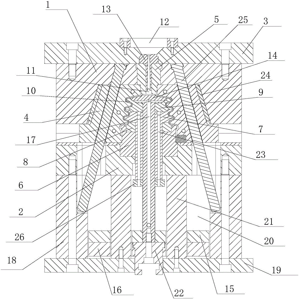
[0018] refer to figure 1 , the present invention proposes a self-ejection dust cover injection mold, including a core assembly, an upper template 1, a lower template 2, an upper mold fixing plate 3, a half block 4, an ejector assembly, and a plurality of inclined guide pillars 25, in:

[0019] The mold core assembly includes an upper mold core 5, a lower mold core 6, and a movable middle mold core 7. The upper mold core 5 is located above the lower mold core 6, and the upper mold core 5 is installed on the upper template 1. The lower mold core 6 is installed on the lower template 2, and the lower mold core 6 upper end is provided with a lower mold core insert 8. The movable core 7 is set in the lower core 6, the upper end of the movable core 7 is provided with a core insert 9, the bottom of the movable core 7 is provided with a limit plate 26, and the movable core 7 is provided with a plurality of The water channels 23 are circumferentially distributed around the central axi...


PUM


Abstract

The invention provides an automatic-ejecting-out injection mold for a dust guard. The automatic-ejecting-out injection mold for the dust guard comprises a mold core assembly, a half block, an upper mold plate, a lower mold plate, an upper mold fixing plate and an ejecting-out assembly. The mold core assembly comprises an upper mold core, a lower mold core and a movable middle mold core, wherein the upper mold core is installed on the upper mold plate which is installed on the upper mold fixing plate, the lower mold core is installed on the lower mold plate, and the movable middle mold core is arranged in the lower mold core. The half block which is arranged around the mold core assembly and matched with the mold core assembly is arranged on the periphery of the mold core assembly, a cavity is formed by the gap between the mold core assembly and the half block, and the upper mold core is provided with a rubber injection hole communicating with the cavity. The ejecting-out assembly comprises an inner ejecting-out mold core, an ejector pin panel and an ejector pin bottom plate, wherein the inner ejecting-out mold core is arranged in the movable middle mold core; the top end of the inner ejecting-out mold core abuts against the upper mold core; the ejector pin panel is located under the lower mold pate; the bottom end of the inner ejecting-out mold core is connected with the ejector pin panel; and the ejector pin panel is installed on the ejector pin bottom plate. The automatic-ejecting-out injection mold for the dust guard can realize automatic production, prolong the service life, and shorten the injection molding period for products.

Description

technical field [0001] The invention relates to the technical field of dust cover moulds, in particular to a self-ejecting dust cover injection mold. Background technique [0002] In the traditional design of the mold structure of injection dust cover, because of the large amount of undercuts of this type of dust cover, demoulding is very difficult. In order to solve the problem of product demoulding and processing, the industry generally uses manual assisted demoulding. The product has large deformation, and at the same time, the labor intensity of manual assisted operation is high and the cycle is long; another way is to use the inner shrinkage mold core structure. The inserts are easy to damage the dust cover. At the same time, because the inner mold core is assembled by multiple inserts, effective cooling cannot be achieved, and the reliability of the mold is low. Contents of the invention [0003] Based on the technical problems in the background technology, the pres...

Claims


Application Information

Patent Timeline
IPC IPC(8): B29C45/27B29C45/33B29C45/40B29C45/43B29C45/73B29C45/78
CPCB29C45/27B29C45/332B29C45/401B29C45/43B29C45/7207B29C45/7312B29C45/78B29C2045/4084B29C2045/7387B29C2945/76531B29C2945/76732
Inventor 李茂华朱静
Owner 安徽宁国中鼎模具制造有限公司
Learn More