Yarn guide device having original-point positioning function

A yarn guide device and origin positioning technology, applied in textiles and papermaking, can solve problems such as inconsistent running directions of timing belts and linear guide rails, high manual maintenance costs, uncontrolled transmission speed, etc., to achieve high quality and stability Automatic winding, high cost of manual maintenance and repair, and the effect of reducing the probability of yarn breakage

Active Publication Date: 2016-10-12
ZHEJIANG JINMA AUTOMATION TECH CO LTD
View PDF6 Cites 2 Cited by
  • Summary
  • Abstract
  • Description
  • Claims
  • Application Information

AI Technical Summary

Problems solved by technology

[0003] In order to solve the above problems, the present invention provides a yarn guide device with the function of origin positioning, which can solve the problems of the existing yarn guide devices, such as the long distance between the yarn guide rod and the center of the synchronous belt, and the running direction of the synchronous belt and the linear guide rail. Inconsistency, the timing belt is easily twisted and the yarn is broken, the cost of manual maintenance is high, the position of the yarn guide rod needs to be manually judged when starting up, the transmission effect is poor, the transmission torque is small, the transmission speed cannot be controlled, and the yarn bobbin is prone to meshing and low work efficiency, it can realize the automatic winding function of high quality and stable yarn, and has the short center distance between the yarn guide rod and the synchronous belt, the running direction of the synchronous belt and the linear guide rail are consistent, the synchronous belt is not easy to twist, Low cost of manual maintenance and repair, no need to manually judge the position of the yarn guide rod when starting up, good transmission effect, large transmission torque, precise control of transmission speed, no webbing on the yarn bobbin, etc., and high work efficiency, etc.

Method used


Image

  • Yarn guide device having original-point positioning function
  • Yarn guide device having original-point positioning function
  • Yarn guide device having original-point positioning function

Examples


Embodiment Construction

[0022] In order to make the technical means, creative features, goals and effects achieved by the present invention easy to understand, the present invention will be further described below in conjunction with specific illustrations.

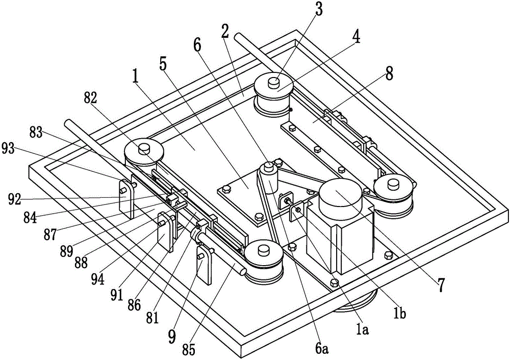
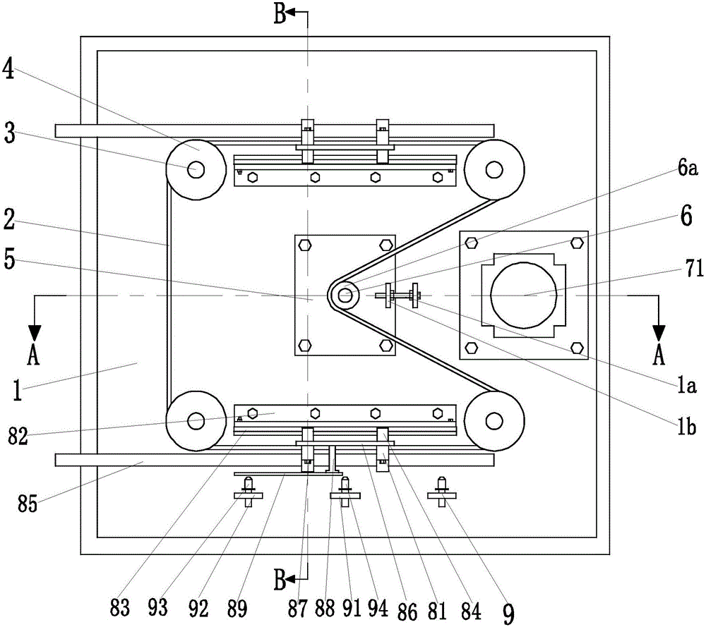
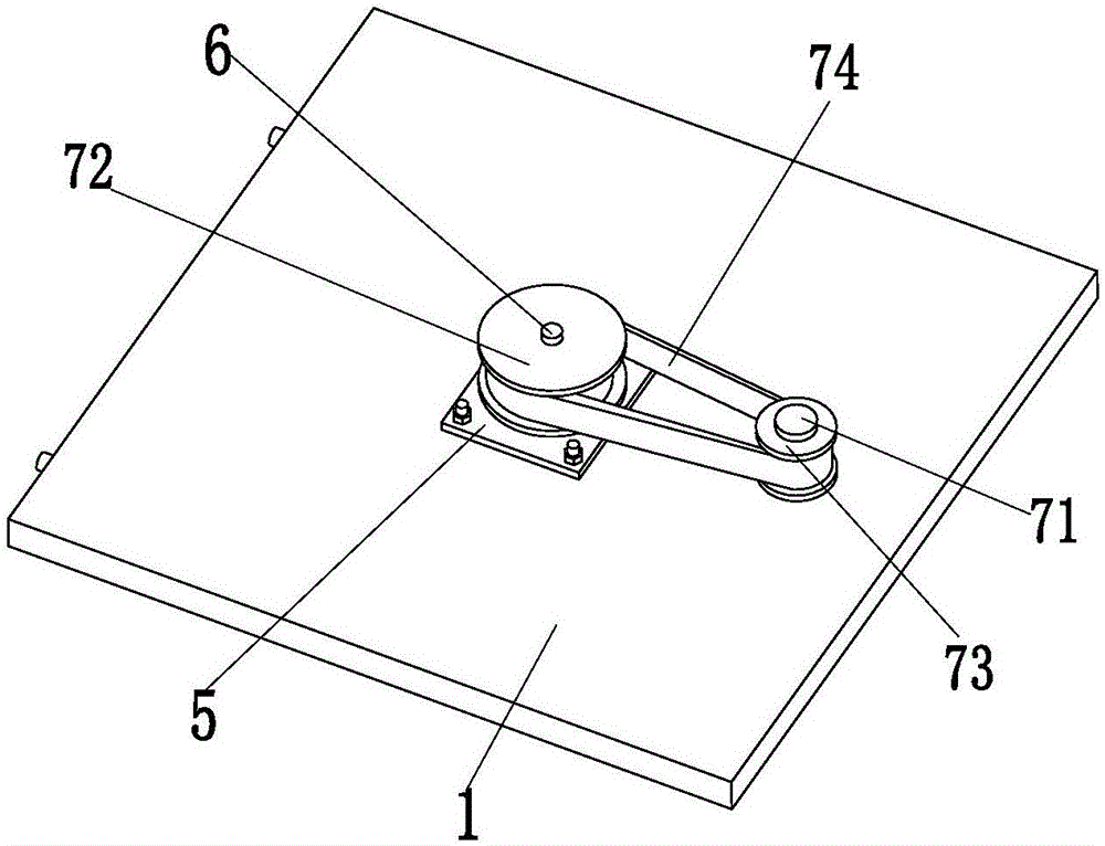
[0023] Such as Figure 1 to Figure 6 As shown, a yarn guide device with origin positioning function includes a base plate 1 and a main timing belt 2. The upper end surface of the base plate 1 is symmetrically welded with four fixed shafts 3, and the four fixed shafts 3 are respectively installed through bearings. There are four transmission pulleys 4, and the four transmission pulleys 4 can stably rotate on four fixed shafts 3 through bearings; the middle part of the base plate 1 is provided with a transmission hole, and the upper and lower ends of the middle part of the base plate 1 are symmetrically installed with two bolts. Mounting plate 5, the drive shaft 6 is installed in the middle of the two mounting plates 5 through bearings, and the mi...


PUM


Abstract

The invention relates to a yarn guide device having an original-point positioning function. The yarn guide device comprises a base plate and a main synchronous belt, wherein four fixing shafts are symmetrically welded on the upper end face of the base plate, four driving belt wheels are respectively installed on the four fixing shafts through bearings, and the four driving belt wheels can stably rotate on the four fixing shafts. Drive holes are formed in the middle of the base plate, two installing plates are symmetrically installed at the upper end and the lower end of the middle of the base plate through bolts, driving shafts are installed in the middles of the two installing plates through bearings, and the middles of the driving shafts penetrates into the drive holes formed in the base plate. The driving belt wheels are installed at the upper ends of the driving shaft in an interference fit mode, and secondary driving branch chains are installed at the lower end of the driving shafts. Two yarn guide branch chains are symmetrically and vertically installed on the front side and the rear side of the base plate through bolts. A sensing branch chain is installed on the front side of the base plate. The yarn guide device can achieve a full-automatic, high-quality and stable yarn winding function.

Description

technical field [0001] The invention relates to the technical field of textile machinery, in particular to a yarn guide device with an origin positioning function. Background technique [0002] The two-for-one twister is composed of a plurality of adjacent spindle positions of the same type. Each spindle position includes two sets of two-for-one twisting devices mainly composed of spindles, traverse guide devices and winding mechanisms. The two sets of two-for-one twisting devices are separately installed on the frame sides. When the two-for-one twister is working, the yarn twisted by the spindle is driven by the friction roller at a certain speed and wound onto the bobbin. During the winding process of the bobbin, the yarn passes through the yarn guide head on the guide rod of the traverse guide device, and the yarn guide rod reciprocates laterally to control the winding angle and winding density of the yarn, so that the yarn spirals Therefore, the traversing yarn guide d...

Claims


Application Information

Patent Timeline
Patent Type & Authority Applications(China)
IPC IPC(8): D01H13/06
CPCD01H13/06
Inventor 杨亚江肖锋滕明阳
Owner ZHEJIANG JINMA AUTOMATION TECH CO LTD
Why Eureka
Try Eureka