Supercharge Your Innovation With Domain-Expert AI Agents!

Gas spring device for warp knitting machine

A gas spring and warp knitting machine technology, which is applied in the field of warp knitting machines, can solve the problems of inaccurate guidance, easy damage, and large wear of guide holes, and achieve the effects of avoiding interference, simplifying difficulty, and improving traversing accuracy

Active Publication Date: 2016-10-12
KARL MAYER CHINA
View PDF6 Cites 0 Cited by
  • Summary
  • Abstract
  • Description
  • Claims
  • Application Information

AI Technical Summary

Problems solved by technology

[0004] In order to overcome the inaccurate guidance of the existing warp knitting machine pattern comb traversing mechanism, and the long-term movement of the steel wire rope will cause greater wear and damage to the guide hole, the invention provides a gas spring device for warp knitting machines

Method used


Image

  • Gas spring device for warp knitting machine
  • Gas spring device for warp knitting machine
  • Gas spring device for warp knitting machine

Examples


Embodiment Construction

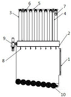
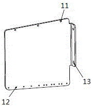
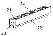
[0020] Such as figure 1 It is a structural diagram of the present invention, a gas spring device for warp knitting machines, including angle iron support 1, gas spring support 2, gas spring column 3, support column 4, gas spring column support plate 5, sleeve 6, piston 7. Drag hook 8, muffler 9 and guide wheel combination 10, the upper end of angle iron support 1 is provided with round hole one 11, the lower end of angle iron support 1 is provided with round hole two 12, and the right side of angle iron support 1 is provided with round hole one. Hole three 13, the middle of the upper surface of the gas spring support 2 is provided with a round hole four 21, the two ends of the upper surface of the gas spring support 2 are provided with threaded holes 2 24, and the side of the gas spring support 2 is provided with a horizontal hole 23 The bottom of the gas spring support 2 is provided with a horizontal threaded hole 22, the gas spring support 2 is fixed above the angle iron sup...


PUM


Abstract

The invention relates to the technical field of warp knitting machines, in particular to a gas spring device for a warp knitting machine. The gas spring device comprises an angle iron support, a gas spring support, gas spring columns, support columns, a gas spring supporting plate, a sleeve, a piston, draw hooks, a silencer and guide wheel binders, wherein round holes I are formed in the upper end of the angle iron support; round holes II are formed in the lower end of the angle iron support; round holes III are formed in the right side of the angle iron support; round holes IV are formed in the middle of the upper surface of the gas spring support; threaded holes II are formed in two ends of the upper surface of the gas spring support; a hole which is transversely through is formed in one side surface of the gas spring support; threaded holes I which are transversely through are formed in the bottom of the gas spring support; the gas spring support is fixed above the angle iron support. The gas spring device can be assembled according to the quantity of actually used steel wires and facilitates standard and modular design; a transparent glass tube is adopted as a gas spring cylinder body, so that problems can be discovered with naked eyes, and debugging and maintenance are facilitated; the transverse moving precision of a wire comb can be improved, and interference between the steel wires is avoided; transverse motion can be transferred more accurately.

Description

technical field [0001] The invention relates to the technical field of warp knitting machines, in particular to a gas spring device for warp knitting machines. Background technique [0002] The pattern comb traverse mechanism of the warp knitting machine is an important part of the warp knitting machine and the main mechanism for weaving different patterns. The multi-bar raschel warp knitting machine achieves the purpose of weaving different patterns by controlling the transverse movement of the pattern bars. The horizontal movement of the patterned comb in the prior art is to connect the left and right ends of the steel wire bar in the patterned comb through the servo motor and the cylinder device respectively, and the motor converts the rotary motion into a linear motion through the disc to drive the transverse movement of the steel wire comb; the cylinder device passes through The movement of the piston controls the traverse of the wire comb from the other side. [0003...

Claims


Application Information

Patent Timeline
Patent Type & Authority Applications(China)
IPC IPC(8): D04B27/26
CPCD04B27/26
Inventor 张凯
Owner KARL MAYER CHINA
Features
  • R&D
  • Intellectual Property
  • Life Sciences
  • Materials
  • Tech Scout
  • Unparalleled Data Quality
  • Higher Quality Content
  • 60% Fewer Hallucinations
Learn More