

Gear shifting zero-crossing switching circuit used for fan or cooling fan
A technology for switching circuits and cooling fans, applied in pump control, non-variable-capacity pumps, machines/engines, etc., can solve problems such as large impact on motor performance, impact on circuit board service life, and large impact on electronic components.
- Summary
- Abstract
- Description
- Claims
- Application Information
AI Technical Summary
Problems solved by technology
Method used
Image

Examples
Embodiment 1
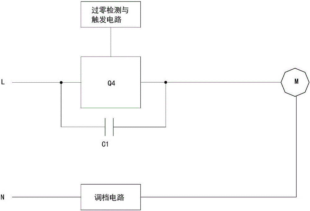
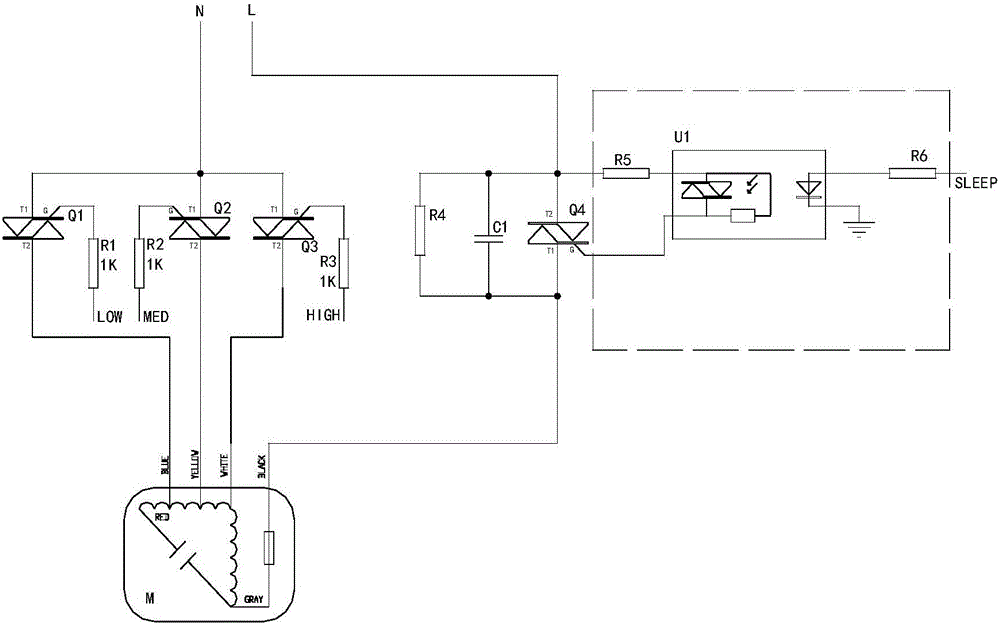
[0015] Such as figure 1 As shown, the zero-crossing switching circuit for adjusting gears for fans or cold fans in this embodiment includes a thyristor switch Q4, a step-down capacitor C1, and a zero-crossing detection and trigger circuit. The step-down capacitor C1 and the thyristor switch Q4 are connected in parallel , The thyristor switch Q4 is arranged in series on the L-phase circuit of the fan or cold fan, the control end of the thyristor switch Q4 is connected with the output end of the zero-crossing detection and trigger circuit, and the two ends of the thyristor switch Q4 are also connected in parallel There is a protection resistor R4. Since the step-down capacitor C1 and the thyristor switch Q4 are connected in parallel, in the normal state, the thyristor switch Q4 is directly turned on, and the short-circuit of the step-down capacitor C1 does not work; when the thyristor switch Q4 is turned off, the voltage is reduced Capacitor C1 works, and the external AC power su...
Embodiment 2
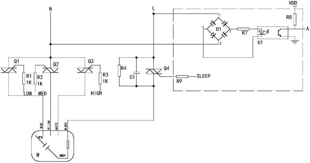
[0019] This embodiment is basically the same as the first embodiment, and the main difference is that the zero-crossing detection and the trigger circuit are different. Such as image 3 As shown, the zero-crossing detection and trigger circuit includes a photocoupler U1, a diode rectifier bridge D1, a third current-limiting resistor R7, a fourth current-limiting resistor R8, and a fifth current-limiting resistor R9. The input end of the diode rectifier bridge D1 and the power supply Connected, the output end of the diode rectifier bridge D1 is connected in series with the third current-limiting resistor R7 and then connected to the primary of the photocoupler U1. One connecting terminal of the secondary of the photocoupler U1 is used as the zero-crossing detection point A and the other connecting terminal is grounded. The zero-crossing detection point A is connected in series with the fourth current-limiting resistor R8 and then connected to the power supply VDD, and the contro...
PUM
 Abstract
Description
Claims
Application Information