
Tension and compression testing machine hydraulic loading system adopting differential control of proportional overflow valves

A proportional relief valve, using proportional technology, is applied in fluid pressure actuators, mechanical equipment, servo motors, etc. It can solve the problems of lack of controllability of micro force, low resolution of output force, and inability to perform synchronous control. Achieve the effects of avoiding poor position adjustment performance, simplifying the hydraulic system, and reducing equipment costs

Inactive Publication Date: 2016-10-12
ZHEJIANG UNIV
View PDF7 Cites 19 Cited by
  • Summary
  • Abstract
  • Description
  • Claims
  • Application Information

AI Technical Summary

Problems solved by technology

[0008] In order to overcome the above-mentioned shortcomings of the existing pressure testing machine loading system that lacks controllability to tiny forces, low output force resolution, and inability to perform synchronous control, the purpose of the present invention is to provide a differential control system using a proportional relief valve. The hydraulic loading system of the tension and compression testing machine has good output force fine-tuning performance and can perform multi-cylinder displacement synchronous control hydraulic system when the hydraulic cylinder is static or quasi-static loading

Method used


Image

  • Tension and compression testing machine hydraulic loading system adopting differential control of proportional overflow valves

Examples


Embodiment Construction

[0021] The present invention will be further described below in conjunction with the accompanying drawings and embodiments.

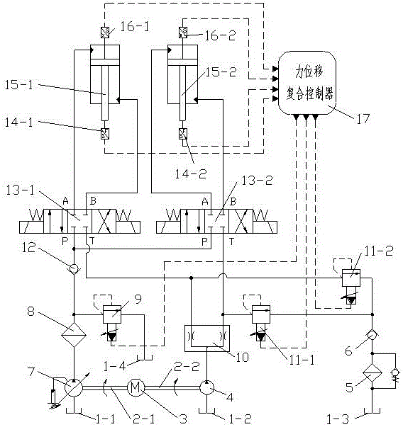
[0022] Such as figure 1 As shown, it includes a hydraulic pump station, a low-pressure filter 5, an oil return check valve 6, a high-pressure proportional relief valve 9, a diverter valve 10, two low-pressure proportional relief valves 11-1, 11-2, and an oil-inlet check valve. Valve 12, two electromagnetic reversing valves 13-1, 13-2, two tension pressure sensors 14-1, 14-2, two hydraulic cylinders 15-1, 15-2, two displacement sensors 16-1, 16-2, force-displacement composite controller 17;

[0023] The A and B oil ports of the two three-position four-way electromagnetic directional valves 13-1 and 13-2 are respectively connected to the rodless cavity and the rod cavity of the respective hydraulic cylinders 15-1 and 15-2, and the two three-position four-way The P ports of the solenoid reversing valves 13-1 and 13-2 are connected and connected in series...


PUM


Abstract

The invention discloses a tension and compression testing machine hydraulic loading system adopting differential control of proportional overflow valves. The system comprises a hydraulic pump station, a low-pressure filter, an oil return one-way valve, the high-pressure proportional overflow valve, a flow dividing valve, the two low-pressure proportional overflow valves, an oil inlet one-way valve, two electromagnetic reversing valves, two tension and compression force sensors, two hydraulic cylinders, two displacement sensors and a force and displacement compound controller. The differential control of the proportional overflow valves and compound control over the pressure and displacement of the hydraulic cylinders by pressure valves are adopted, and the micro force control and loading force control precision of a testing machine is improved; and during static and quasi-static loading of the tension and compression force testing machine, the loading force and the hydraulic cylinder synchronous displacement in the loading process are controlled in real time, and control over any loading curve and synchronous control over the multiple hydraulic cylinders are achieved. By means of the tension and compression testing machine hydraulic loading system adopting differential control of the proportional overflow valves, the tension and compression testing machine can adapt to various complicated loading work conditions. The tension and compression testing machine hydraulic loading system adopting differential control of the proportional overflow valves is suitable for the occasion where the loading force changing range is wide, the adjusting precision is high, and the hydraulic cylinders frequently need to perform synchronous control during static and quasi-static loading.

Description

technical field [0001] The invention relates to hydraulic transmission and control technology, in particular to a hydraulic loading system of a tensile and compression testing machine adopting differential control of a proportional overflow valve. Background technique [0002] Large-scale compression (tension) testing machine is an important equipment in national production. It is widely used in mechanical performance tests of engineering materials such as metals and concrete, and loading simulation tests to verify the reliability of equipment in complex working conditions such as oil fields and deep seas. The equipment often requires both large output force and small pressure control accuracy, and its control performance has an important impact on the test results. [0003] At present, almost all large-scale pressure (tensile) testing machines are loaded and driven by hydraulic cylinders, and there are mainly two ways to control the pressure of hydraulic cylinders: servo va...

Claims


Application Information

Patent Timeline
IPC IPC(8): F15B11/22F15B13/06F15B13/16
CPCF15B11/22F15B13/06F15B13/16F15B2211/205
Inventor 周华姚叶明陈英龙
Owner ZHEJIANG UNIV
Learn More