One-way clutch bearing

A technology of one-way clutches and bearings, which is applied in the direction of one-way clutches, clutches, bearings, etc., can solve the problems of unguaranteed product quality, complicated processing technology, and difficult production technology, and achieves wide application range, good processing technology, and structural simple compact effect

Active Publication Date: 2016-10-12
WUXI NO 2 BEARING
View PDF18 Cites 0 Cited by
  • Summary
  • Abstract
  • Description
  • Claims
  • Application Information

AI Technical Summary

Problems solved by technology

At present, the basic principles of the one-way clutch bearings at home and abroad to realize the one-way function mainly include the following schemes: a structure such as figure 1 As shown, the raceways of the inner and outer rings of the one-way clutch bearing are circular, and the stop in the middle is a detent that forms a parabolic shape on the outside; another structure is as follows figure 2 As shown, the inner ring and rolling outer circle of the one-way clutch bearing are circular, and the raceway of the outer ring is multi-shaped; there is also a structure such as image 3 As shown, the outer diameter of the outer ring raceway and the rolling body is circular, and the inner ring raceway is made into a multi-tap shape. The principle of realizing one-way is to rely on the wedge-shaped part on the inner ring raceway to realize the stop. This strange shape The characteristics of the production process have brought great difficulties
To sum up, in the above-mentioned several structures, whether it is to set multi-slip grooves on the inner ring or outer ring, or to make the rolling elements into a parabolic shape, the processing technology is very complicated, and the precision is poor, and the product quality cannot be guaranteed.

Method used


Image

  • One-way clutch bearing
  • One-way clutch bearing
  • One-way clutch bearing

Examples


Embodiment Construction

[0022] The specific embodiments of the present invention will be further described below in conjunction with the accompanying drawings.

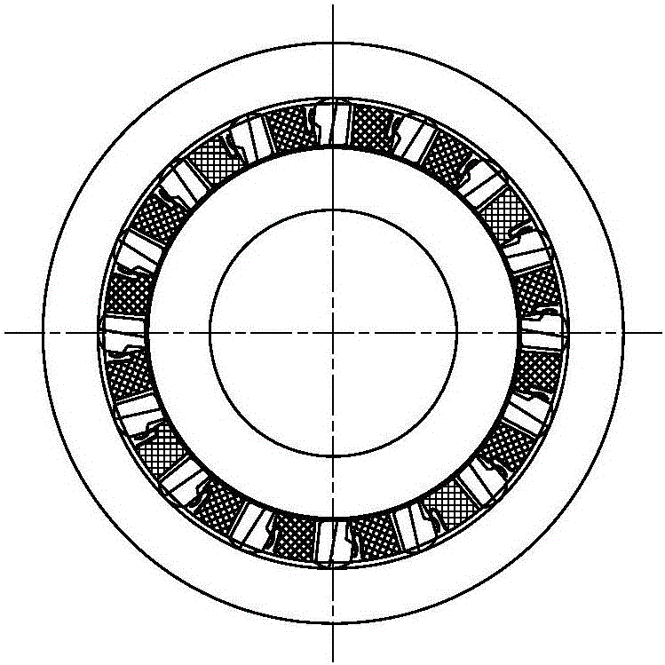
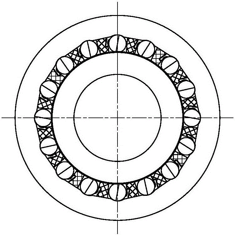
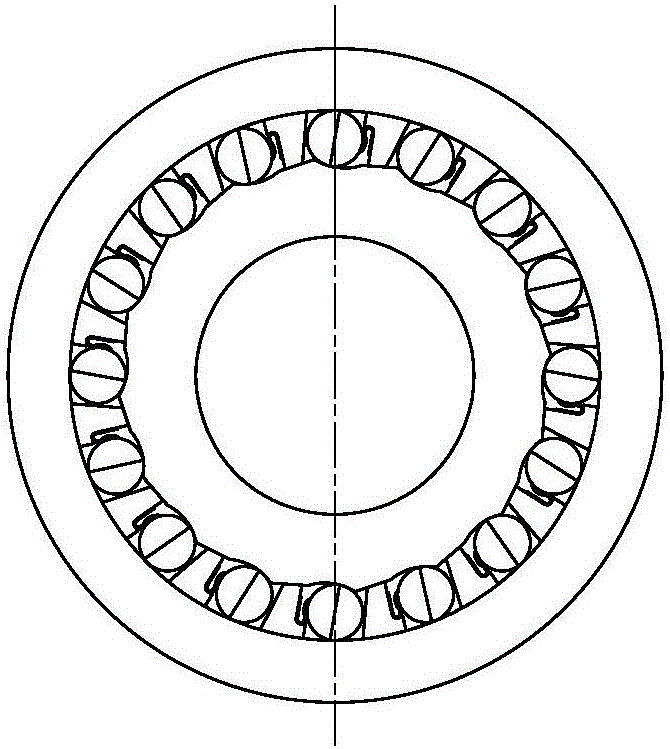
[0023] like Figure 4~Figure 6 As shown, the one-way clutch bearing in the embodiment is mainly composed of an outer ring 1, an inner ring 2 and a rolling support structure arranged between the two. The rolling support structure is mainly composed of a rolling body 3, a rolling body cage 4, The needle roller cage 5 and the needle roller group are composed.

[0024] like Figure 4~Figure 6 As shown, the outer ring 1 and the inner ring 2 are axially divided into a rolling element installation section a and a needle roller installation section b, and rolling element installation sections a are provided with rollers on the inner wall of the outer ring 1 and the outer wall of the inner ring 2 Several rolling elements 3 are arranged in the raceway on the outer ring 1 and the inner ring 2, and the rolling element cage 4 evenly separates the sever...


PUM


Abstract

The invention relates to a one-way clutch bearing. In the axial direction, an outer ring and an inner ring are divided into a rolling body mounting section and a rolling needle mounting section; a roller path is arranged on the outer ring inner wall and the inner ring outer wall of the rolling body mounting section; a plurality of rolling bodies are arranged in the roller path on the outer ring and the inner ring; a rolling body holder is used for uniformly separating the plurality of the rolling bodies; a plurality of rolling needle groups are arranged between the outer ring inner wall and the inner ring outer wall of the rolling needle mounting section; a rolling needle holder is used for uniformly separating the plurality of the rolling needle groups; each rolling needle group comprises a first rolling needle and a second rolling needle; each first rolling needle and each second rolling needle are arranged in a holding slot of the rolling needle holding frame; a pressure angle is formed between a center connecting line of the first rolling needle and the second rolling needle and a contact pressure direction of the inner ring; each first rolling needle is positioned at the radial inner end of the holding slot, and is in contact with the outer wall of the inner ring; and each second rolling needle is positioned at the radial outer end of the holding slot, and is in contact with the inner wall of the outer ring. The one-way clutch bearing is simple and compact in structure, is good in processing process and is high in precision; and product quality is guaranteed.

Description

technical field [0001] The invention relates to a one-way clutch bearing. Background technique [0002] One-way clutch bearing is a kind of bearing, which is characterized by the function of one-way rotation and reverse stop, and is widely used in one-way clutches of washing machines, one-way clutches of automobiles and one-way clutches of electric automatic vehicles. At present, the basic principles of the one-way clutch bearings at home and abroad to realize the one-way function mainly include the following schemes: a structure such as figure 1 As shown, the raceways of the inner and outer rings of the one-way clutch bearing are circular, and the stop in the middle is a detent that forms a parabolic shape on the outside; another structure is as follows figure 2 As shown, the inner ring and rolling outer circle of the one-way clutch bearing are circular, and the raceway of the outer ring is multi-shaped; there is also a structure such as image 3 As shown, the outer diam...

Claims


Application Information

Patent Timeline
Patent Type & Authority Applications(China)
IPC IPC(8): F16D41/064F16C19/49F16C33/78F16C33/58
CPCF16C19/492F16C33/583F16C33/7809F16D41/064F16D2041/0646F16C2361/43F16C41/001F16C19/06F16D41/073
Inventor 谭义银
Owner WUXI NO 2 BEARING
Why Eureka
Try Eureka