A limit device for high-temperature reheat steam pipeline and its arrangement method

A steam pipeline, high-temperature reheating technology, applied in pipeline systems, pipeline supports, pipes/pipe joints/pipe fittings, etc., can solve the problems that the support and hanger structure cannot be generalized, the overall structure is unreasonable, and the investment cost is high. The effect of reducing the difficulty of distributed computing, wide application and good stability

Active Publication Date: 2019-07-19
CHINA ENERGY ENG GRP GUANGDONG ELECTRIC POWER DESIGN INST CO LTD
View PDF6 Cites 0 Cited by
  • Summary
  • Abstract
  • Description
  • Claims
  • Application Information

AI Technical Summary

Problems solved by technology

[0004] One of the purposes of the present invention is to solve the problems of unreasonable overall structure, generalization of support and hanger structure, low laying efficiency and high investment cost in the existing high-temperature reheat steam pipe upper limit device designed only by experience , providing a limit device for high temperature reheat steam pipeline

Method used


Image

  • A limit device for high-temperature reheat steam pipeline and its arrangement method
  • A limit device for high-temperature reheat steam pipeline and its arrangement method
  • A limit device for high-temperature reheat steam pipeline and its arrangement method

Examples


specific Embodiment 1

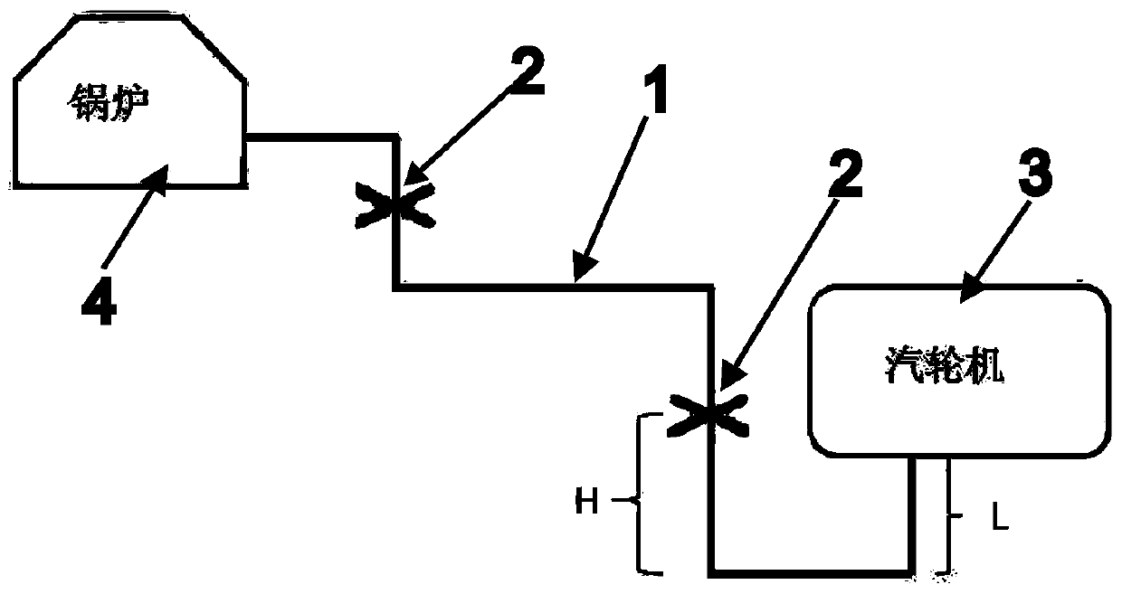
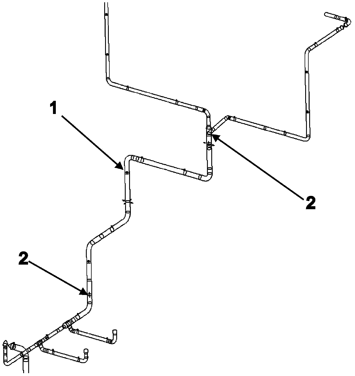
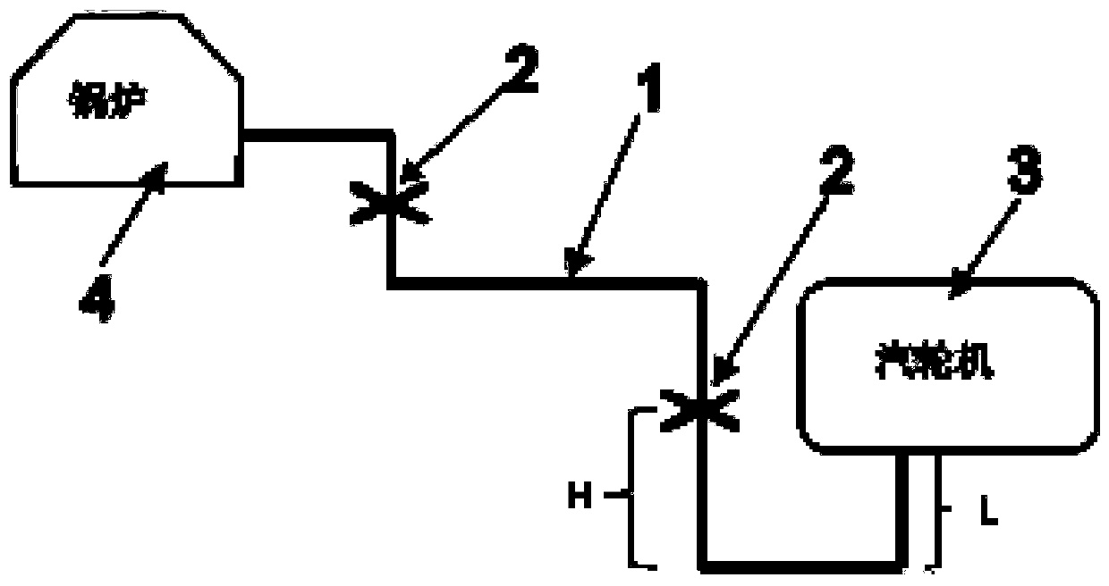
[0029] Reference figure 1 with figure 2 , This embodiment relates to a high-temperature reheat steam pipe limiting device, including a high-temperature reheat steam pipe 1 and equipment connected to the two ends of the high-temperature reheat steam pipe. A number of axial directions are provided on the high-temperature reheat steam pipe 1. The stopper 2 uses the thermal expansion characteristics of the pipeline itself to offset the thermal displacement of the equipment interface. The axial stopper 2 is arranged near the connection between the high-temperature reheat steam pipeline 1 and the equipment to reduce the high-temperature reheat steam pipeline system The overall thrust and thrust distance generated by the device interface; the number of axial stoppers 2 is the same as the number of interfaces connected to the high-temperature reheat steam pipe 1, which is 1-5; the setting position of the axial stopper 2 is determined by The expression H=Z / (T×α)+L is determined. In the...

specific Embodiment 2

[0060] The specific embodiment 2 of the present invention is characterized in that the axial stopper 2 is an axial reinforcement provided on the high-temperature reheat steam pipe 1 to limit the axial expansion and contraction of the high-temperature reheat steam pipe 1. The rest is the same as in Example 1.


PUM


Abstract

The invention relates to a limiting device for a high-temperature reheat steam pipeline and an arranging method of the limiting device. The limiting device comprises the high-temperature reheat steam pipeline and equipment connected to two ends of the high-temperature reheat steam pipeline; several axial limiters are arranged on the high-temperature reheat steam pipeline to offset thermal displacement at equipment interfaces by utilizing the thermal expansion property of the high-temperature reheat steam pipeline itself; the axial limiters are arranged near the parts, connected with the equipment, of the high-temperature reheat steam pipeline; the number of the axial limiters is 1 to 5 or the same number as that of the interfaces of the equipment connected with the high-temperature reheat steam pipeline; and the positions of the axial limiters are determined by the expression H=Z / (T*alpha)+L. The limiting device has the beneficial effects that universalization is realized; the problems of low laying efficiency and high investment are solved; the distribution computing difficulty of the limiting device is reduced; the mounting stability of the high-temperature reheat steam pipeline as well as the safety of equipment running can be improved; the design of supports and hangers of the high-temperature reheat steam pipeline is standardized and unified; and the application range is wide.

Description

Technical field [0001] The invention relates to a limit device for a high-temperature reheat steam pipeline and an arrangement method thereof, and is suitable for laying of the high-temperature reheat steam pipeline of a thermal power generating set. It belongs to the technical field of thermal power plant equipment. Background technique [0002] The high-temperature reheat steam pipeline is also called the reheat section pipeline, and the distribution reheat section pipeline in the power plant is collectively called the piping system. It is the steam pipeline from the boiler reheater outlet in the thermal power plant to the front of the Zhonglian Gate. Due to the high design temperature of the high-temperature reheat steam pipeline, the pipe diameter is relatively large, and the pipeline deformation is relatively large under working conditions. In addition, there is a large Z-direction thermal displacement of the steam turbine central coupling, which will cause the high-temperat...

Claims


Application Information

Patent Timeline
Patent Type & Authority Patents(China)
IPC IPC(8): F17D1/06F16L3/00
CPCF16L3/00F17D1/06
Inventor 席琛李航
Owner CHINA ENERGY ENG GRP GUANGDONG ELECTRIC POWER DESIGN INST CO LTD
Why Eureka
Try Eureka