Wall-mounted air intake fan

A kind of air inlet and wall-mounted technology, which is applied in heating mode, ventilation system, mechanical equipment, etc. It can solve the problems of closed structure, easy cleaning and replacement, and unsatisfactory noise.

Active Publication Date: 2016-10-12
FUJIAN ALLEN ELECTRONICS
View PDF26 Cites 5 Cited by
  • Summary
  • Abstract
  • Description
  • Claims
  • Application Information

AI Technical Summary

Problems solved by technology

[0002] The fresh air system is based on sending fresh air to the room with special equipment (such as an intake fan) on one side of the closed room, and then exhausting it from the other side to the outside by special equipment (such as an exhaust fan). A "fresh air flow field" will be formed indoors. In order to meet the needs of indoor fresh air ventilation, people's understanding of the equipment of the fresh air system is still the traditional installation of relatively large air intake, purification and exhaust equipment indoors, and the pre-buried layout of various connecting pipelines. This kind of system is a big project, which requires major changes and special personnel to maintain and clean up, which is very troublesome. Of course, this kind of system is suitable for use in large spaces, but for smaller spaces, such as family rooms, small studios, etc. Whether it is air intake, purification equipment, or exhaust equipment, what people pursue is first the air purification treatment effect of the equipment, and then the equipment is easy to clean and replace, and the shape and structure. Although some existing air intake fans are small in size, However, it is not ideal in terms of appearance, airtight structure, easy cleaning, easy replacement, and noise.

Method used


Image

  • Wall-mounted air intake fan
  • Wall-mounted air intake fan
  • Wall-mounted air intake fan

Examples


Embodiment Construction

[0029] In order to further explain the technical solution of the present invention, the present invention will be described in detail below through specific examples.

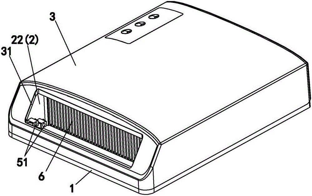
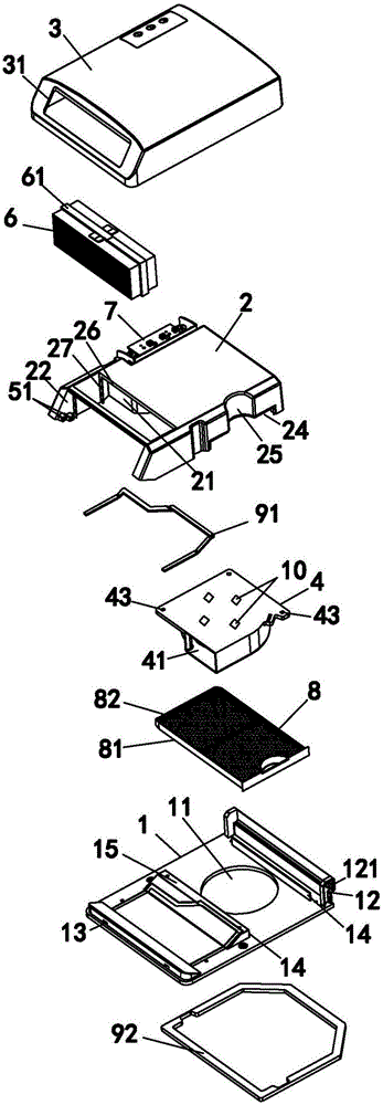
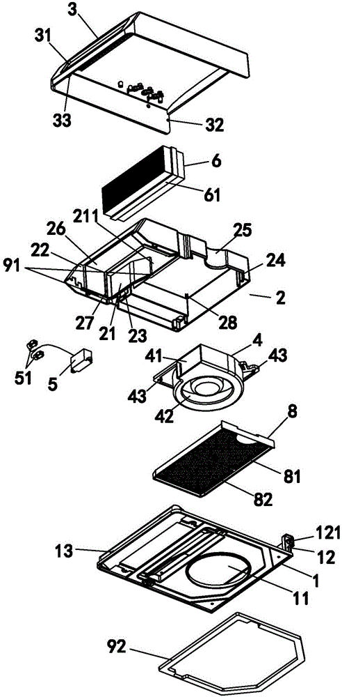
[0030] A wall-mounted air intake fan disclosed by the present invention includes a mounting base 1, an inner casing 2, an outer casing 3, an exhaust fan 4, an anion generator 5, an air outlet filter 6 and a control module 7; figure 1 , figure 2 and image 3 The shown details describe the positional connection relationship between the components.

[0031] As shown in the figure, the exhaust fan 4, the negative ion generator 5 and the air outlet filter 6 are arranged on the inner casing 2, and the inner casing 2 is provided with a partition 21, and the partition 21 divides the interior The casing 2 is divided into two areas respectively provided with an exhaust fan 3 and an air outlet filter 6, and the partition 21 is provided with a connecting port 211 for connecting with the air outlet 41 of the exhaust fan ...


PUM


Abstract

The invention discloses a wall-mounted air intake fan which comprises a mounting base, an inner shell, an outer shell, an exhaust fan, a negative-ion generator, an air outlet filter and a control module. The exhaust fan, the negative-ion generator and the air outlet filter are arranged on the inner shell. A partition plate is arranged on the inner shell to divide the inner shell into two areas. The partition plate is provided with a connector connected with an air outlet of the exhaust fan. An inner exhaust opening is formed in the position, corresponding to the air outlet filter, of the inner shell. The inner shell is locked and fixed to the mounting base. Probes of the negative-ion generator are arranged on the inner exhaust opening. An air intake opening corresponding to an air inlet is formed in the mounting base. The outer shell is arranged outside the inner shell in a covering manner and connected with the mounting base. The control module is arranged in the outer shell. An outer exhaust opening is formed in the position, corresponding to the inner exhaust opening, of the outer shell. The exhaust fan and the negative-ion generator are connected with the control module. The air intake fan of the structure is especially suitable for being arranged in a small space room for use, has a good air purification effect and is convenient to clean and replace.

Description

technical field [0001] The invention relates to the field of air purification equipment, in particular to a wall-mounted air intake fan in a fresh air system. Background technique [0002] The fresh air system is based on sending fresh air to the room with special equipment (such as an intake fan) on one side of the closed room, and then exhausting it from the other side to the outside by special equipment (such as an exhaust fan). A "fresh air flow field" will be formed indoors. In order to meet the needs of indoor fresh air ventilation, people's understanding of the equipment of the fresh air system is still the traditional installation of relatively large air intake, purification and exhaust equipment indoors, and the pre-buried layout of various connecting pipelines. This kind of system is a big project, which requires major changes and special personnel to maintain and clean up, which is very troublesome. Of course, this kind of system is suitable for use in large space...

Claims


Application Information

Patent Timeline
Patent Type & Authority Applications(China)
IPC IPC(8): F24F7/013F24F13/28F24F13/20F24F11/02F24F3/16F24F13/24
CPCF24F7/013F24F11/89F24F13/20F24F13/24F24F13/28F24F2013/207F24F2013/205F24F2013/247F24F8/30F24F8/192F24F8/10
Inventor 陈芳林
Owner FUJIAN ALLEN ELECTRONICS
Why Eureka
Try Eureka