Catenary dynamic detection system

A dynamic detection and catenary technology, applied in measuring devices, instruments, etc., can solve problems such as low monitoring efficiency and achieve the effect of improving detection efficiency

Active Publication Date: 2018-11-30
成都骏盛科技有限责任公司
View PDF6 Cites 0 Cited by
  • Summary
  • Abstract
  • Description
  • Claims
  • Application Information

AI Technical Summary

Problems solved by technology

[0009] The purpose of the present invention is to provide a catenary dynamic detection system to solve the problem of low monitoring efficiency of existing catenary dynamic detection equipment

Method used


Image

  • Catenary dynamic detection system

Examples


Embodiment Construction

[0015] The specific embodiments of the present invention are described below so that those skilled in the art can understand the present invention, but it should be clear that the present invention is not limited to the scope of the specific embodiments. For those of ordinary skill in the art, as long as various changes Within the spirit and scope of the present invention defined and determined by the appended claims, these changes are obvious, and all inventions and creations using the concept of the present invention are included in the protection list.

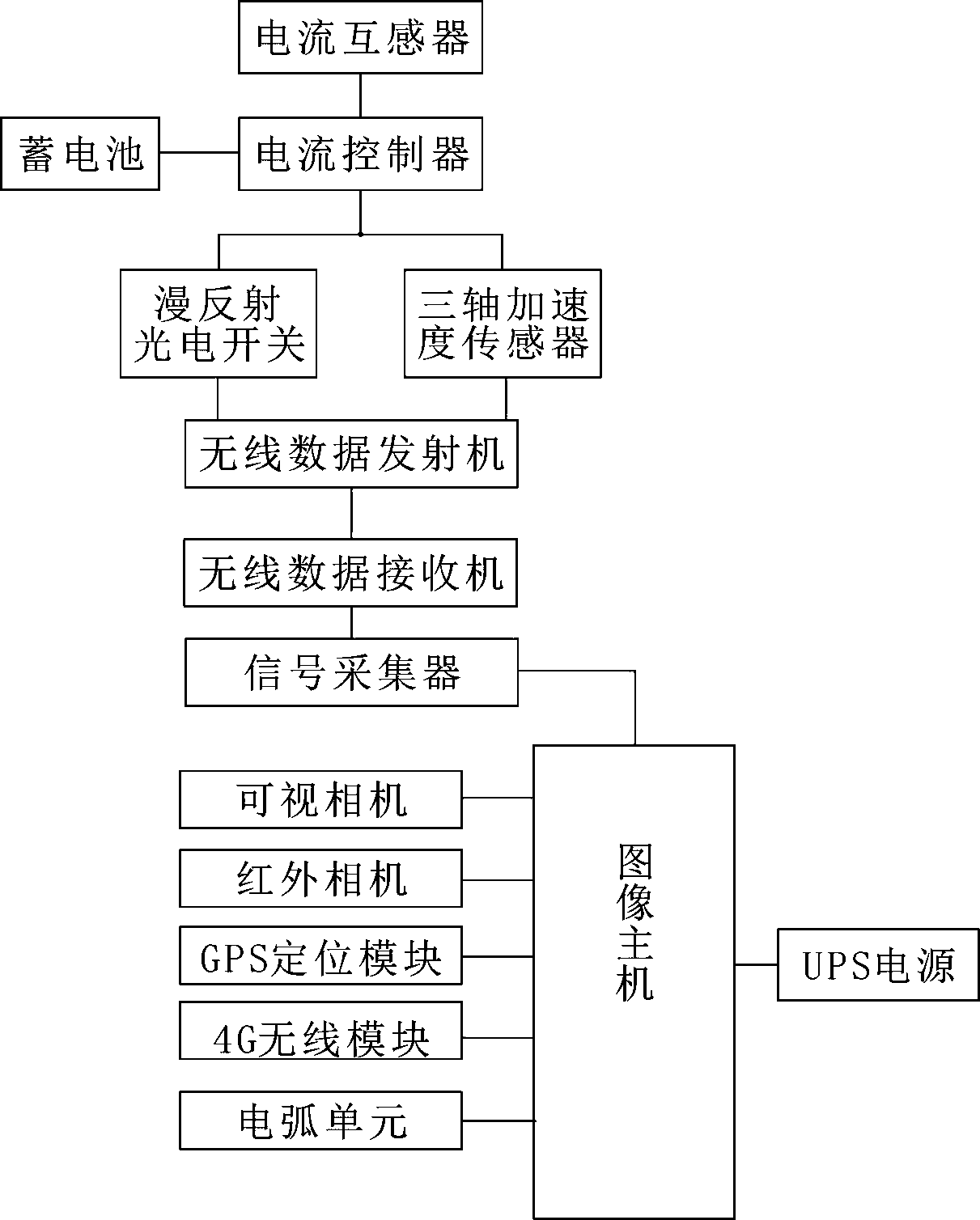
[0016] Such as figure 1 The catenary dynamic detection system shown includes the high-voltage data acquisition part set on both sides of the locomotive roof, the low-voltage data acquisition part set in the middle of the locomotive roof, and the data processing part set in the locomotive; the following are respectively A detailed description of each part:

[0017] The high-voltage data acquisition part includes a storage b...


PUM


Abstract

The invention discloses a dynamic detection system of an overhead line system. The dynamic detection system comprises high pressure data collection portions arranged on the two sides of the roof of a locomotive, a low pressure data collection portion arranged in the middle of the roof of the locomotive, and a data processing portion arranged inside the locomotive. Each high pressure data collection portion comprises a storage battery, a current controller electrically connected with the storage battery, a current transformer, a stagger value detection unit and a hard spot detection unit, wherein the current transformer, the stagger value detection unit and the hard spot detection unit are connected with the current controller. The low pressure data collection portion comprises a visual camera, an infrared camera, a GPS positioning module, a 4G wireless module and an electric arc unit which are connected with the data processing unit. The data processing portion comprises an image processing host, a signal collector and a UPS, wherein the signal collector and the UPS power source are connected with the image processing host. The system can achieve online detection of the overhead line system and a bow net operation state in real time in an all-weather mode and can timely find abnormal defects existing in the overhead line system.

Description

technical field [0001] The invention relates to a catenary dynamic detection system. Background technique [0002] In the electrified railway, the catenary is the main power supply equipment of the electrified railway, and the electric locomotive obtains electric energy through the catenary. Pantograph-catenary relationship plays an important role in the normal operation of the entire electrified railway operation system. In order to ensure the reliability of catenary operation and the good current receiving performance between pantograph and catenary, it is very important to detect the relationship between pantograph and catenary and grasp the status of catenary parameters at any time. The catenary carries a huge traction current during operation, and faulty catenary wire clamps and other parts may cause temperature anomalies, catenary geometric parameters exceeding limits, etc., which may cause catenary failures. Since the catenary has no backup equipment, once a fault o...

Claims


Application Information

Patent Timeline
Patent Type & Authority Patents(China)
IPC IPC(8): G01D21/02
CPCG01D21/02
Inventor 游诚曦尹开华
Owner 成都骏盛科技有限责任公司
Why Eureka
Try Eureka