Adaptive infrared non-uniformity calibration method based on motion state estimation

A non-uniformity correction, motion state technology, applied in radiation pyrometry, measuring devices, instruments, etc., can solve the problems of high algorithm complexity, inconvenient operation, poor real-time performance, etc., achieve low algorithm complexity, power-on The effect of short preparation time and large dynamic range

Active Publication Date: 2016-10-12
SHANGHAI AEROSPACE CONTROL TECH INST
View PDF6 Cites 11 Cited by
  • Summary
  • Abstract
  • Description
  • Claims
  • Application Information

AI Technical Summary

Problems solved by technology

[0003] In the prior art, calibration-based non-uniformity correction algorithms, such as two-point correction and segmental correction, are commonly used in domestic calibration methods for infrared imaging detectors. Such algorithms are simple in calculation and fast in correction speed, but require complicated Periodic calibration maintenance for calibration equipment is inconvenient and expensive
In the prior art, there are also scene-based non-uniformity correction methods such as time-domain high-pass filtering method, neural network method, and image registration method, but such methods have high algorithm complexity, poor real-time performance, ghost defects, and difficult engineering implementation

Method used


Image

  • Adaptive infrared non-uniformity calibration method based on motion state estimation
  • Adaptive infrared non-uniformity calibration method based on motion state estimation
  • Adaptive infrared non-uniformity calibration method based on motion state estimation

Examples


Embodiment Construction

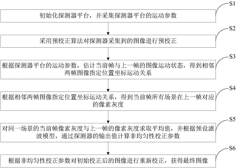
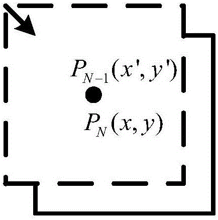
[0030] The present invention will be further elaborated below by describing a preferred specific embodiment in detail in conjunction with the accompanying drawings.

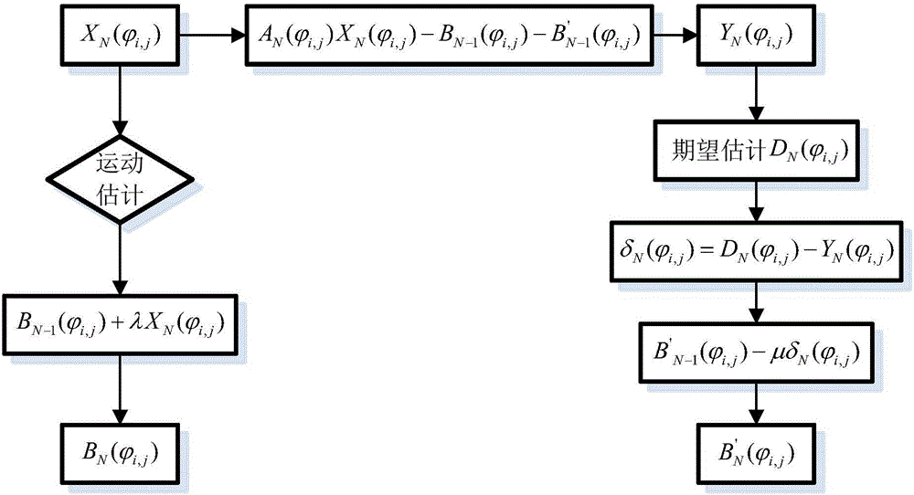
[0031] The non-uniformity of infrared detectors can be divided into intrinsic non-uniformity and additive inhomogeneity Indicates the inhomogeneity caused by the inherent characteristics of the detector element, the inherent characteristics of the optical system, etc.; Indicates the non-uniformity caused by changes in detector sensitivity, optical system aging, and changes in circuit characteristics. From the perspective of non-uniformity correction (NUC), the and Further classification, the establishment of the following mathematical model:

[0032] The first category is the spatial non-uniformity R ij , showing that under the same irradiance conditions, the gray values ​​corresponding to different pixels of the image at the same time are not equal; the second type is the time non-uniformity R t , w...


PUM


Abstract

The invention discloses an adaptive infrared non-uniformity calibration method based on motion state estimation. The method includes the steps of initializing a detector platform, acquiring motion parameters of the detector platform, pre-calibrating images acquired by a detector through a precalibration algorithm, estimating the image motion states of the current frame and the previous frame according to the motion parameters of the detector platform to obtain the designated position coordinate motion relation of images of adjacent two frames, obtaining the corresponding pixel gray scale of all scenes of the current frame in the previous frame according to the designated position coordinate motion relation of images of adjacent two frames, obtaining the average value of the current frame pixel gray scale and previous frame pixel gray scale of a same scene, calculating non-uniformity calibration parameters through output values of the detector according to a preset filtering model, and and re-calibrating the initially calibrated images according to the non-uniformity calibration parameters to obtain a final image. Time drift and temperature drift problems of a detector can be effectively solved.

Description

technical field [0001] The invention relates to the technical field of non-uniformity correction, in particular to an adaptive infrared non-uniformity correction method based on motion state estimation, which is applied to an infrared imaging system. Background technique [0002] Infrared images are being used more and more widely and deeply in military, civil and medical fields. At the same time, people have higher and higher requirements for images in infrared imaging systems. Due to many uncontrollable factors and the limitations of the technological level, the non-uniformity of infrared images seriously affects the image quality and becomes a serious problem that limits the application of infrared detectors in all aspects. Therefore, for high-quality infrared imaging systems, non-uniformity correction technology is one of the most critical image processing technologies. [0003] In the prior art, calibration methods for infrared imaging detectors in China generally use...

Claims


Application Information

Patent Timeline
Patent Type & Authority Applications(China)
IPC IPC(8): G01J5/00
CPCG01J5/00G01J5/80
Inventor 杨俊彦曹耀心刘滨
Owner SHANGHAI AEROSPACE CONTROL TECH INST
Why Eureka
Try Eureka