A heat transfer oil sampler for a boiler

A heat-conducting oil and sampler technology, applied in the boiler field, can solve problems such as complex structure, poor safety, and burns of sampling personnel, and achieve the effects of accurate sampling data, high safety in use, and convenient operation

Active Publication Date: 2019-05-03
ZHEJIANG TUFF BOILER
View PDF6 Cites 0 Cited by
  • Summary
  • Abstract
  • Description
  • Claims
  • Application Information

AI Technical Summary

Problems solved by technology

The accumulation of oil coke and carbon scale on the heat transfer tube wall of the heat transfer oil boiler will not only greatly reduce the heat transfer efficiency, increase the fuel cost, but also affect the temperature of the downstream production process
In severe cases, it will cause local overheating of the heat transfer wall, cracks, corrosion and pipe explosion on the pipe wall, and the leakage of heat transfer oil will cause major safety accidents such as fire and casualties.
Because the relevant specifications for the inspection of heat-conducting oil boilers require that the heat-conducting oil boiler system should be equipped with at least one heat-conducting oil sampling and cooling device, but the heat-conducting oil samplers used in the actual inspection work are all cooled by water cooling, not only the structure is complex, A large amount of water is required for circulating cooling every time, and due to the high temperature of the heat transfer oil, a large amount of high-temperature steam is easily generated during the water cooling process, which may cause burns to the sampling personnel, and the safety is poor

Method used


Image

  • A heat transfer oil sampler for a boiler
  • A heat transfer oil sampler for a boiler
  • A heat transfer oil sampler for a boiler

Examples


Embodiment Construction

[0026] The following are specific embodiments of the present invention and in conjunction with the accompanying drawings, the technical solutions of the present invention are further described, but the present invention is not limited to these embodiments.

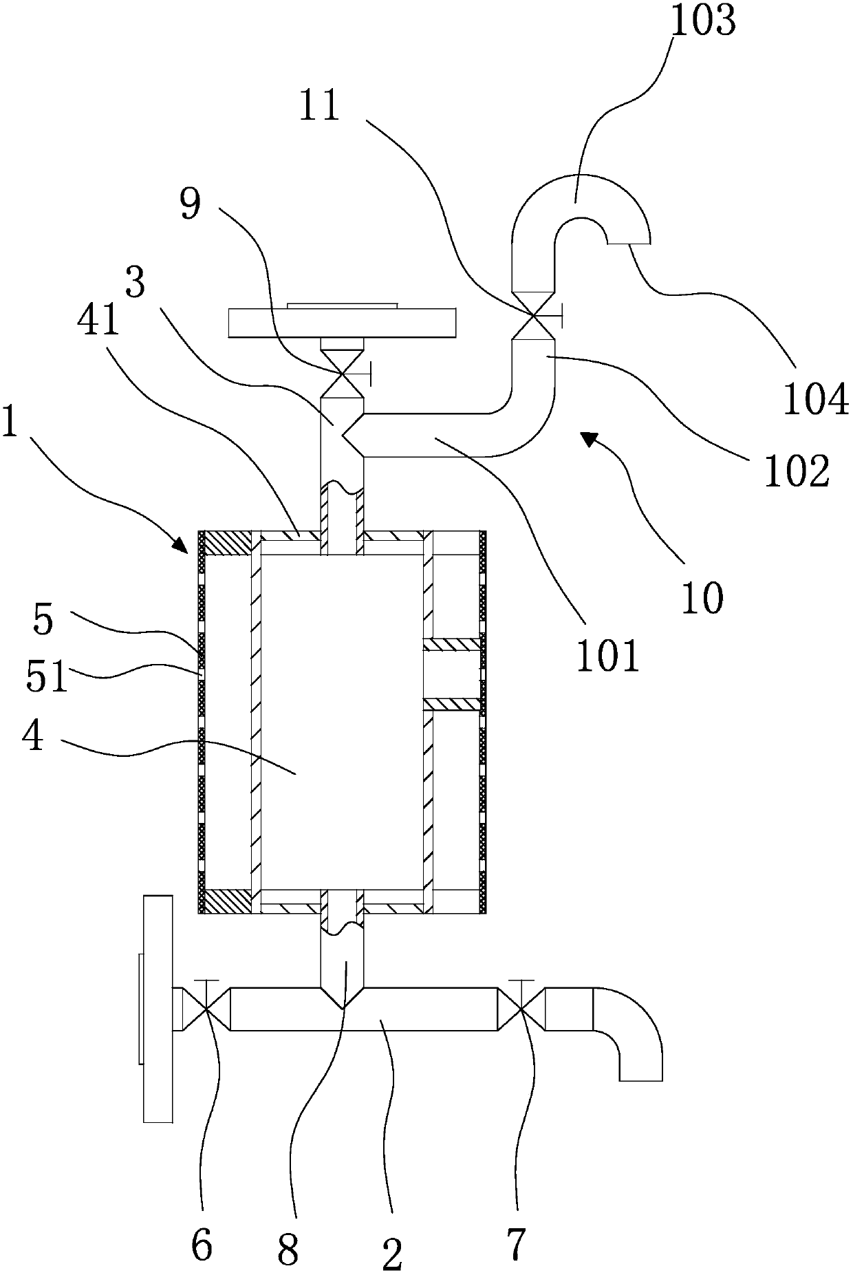
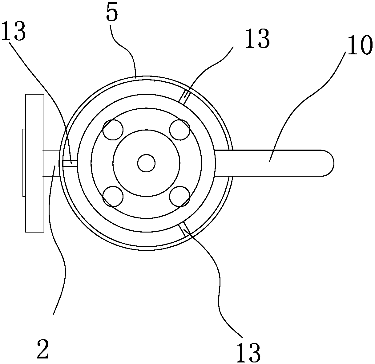
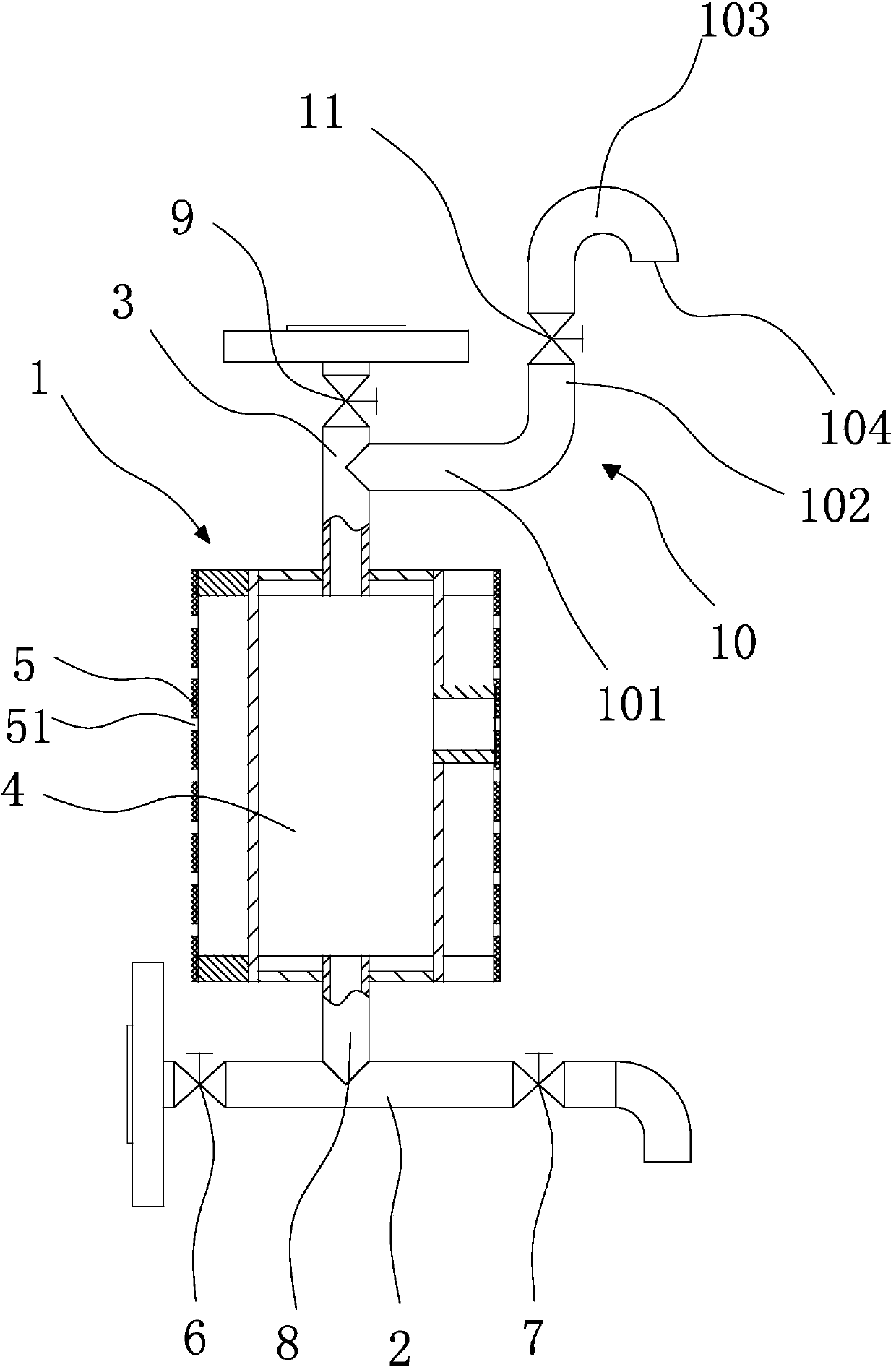
[0027] refer to figure 1 and figure 2 , This embodiment is a heat transfer oil sampler for boilers, including a cooling cylinder 1, a sampling pipe 2, an oil return pipe 3, a connecting pipe 8, an oil return valve 9, an exhaust pipe 10 and an exhaust valve 11. The cooling cylinder 1 includes a core tube 4 for cooling heat transfer oil and an orifice plate 5 in a cylindrical structure surrounding the outside of the core tube 4. Several ventilation holes 51 are opened on the orifice plate 5, and the orifice plate 5 and the core tube 4 There is a gap between the outer walls.

[0028] The sampling tube 2 is arranged horizontally and is located below the core tube 4, and the sampling tube 2 and the core tube 4 are connected ...


PUM


Abstract

The invention provides a conduction oil sampler for a boiler and a sampling method, and belongs to the technical field of boilers. The conduction oil sampler solves the problem that existing conduction oil sampling for a boiler is not convenient and low in safety. The conduction oil sampler for the boiler comprises a cooling cylinder, a sampling tube and an oil return tube. The cooling cylinder comprises a core cylinder for cooling conduction oil and a pore plate arranged on the outer side of the core cylinder in a defined mode, a plurality of vent holes are formed in the pore plate, an oil conducting valve is arranged at one end of the sampling tube, and a sampling valve is arranged at the other end of the sampling tube; the sampling tube and the core cylinder are communicated through a vertically-arranged connecting tube, one end of the oil return tube is connected to the top end of the core cylinder, the oil return tube is communicated with the core cylinder, and an oil return valve is arranged at the other end of the oil return tube. During sampling, high-temperature conduction oil in the boiler is conveyed into the core cylinder for standing air-cooling; after cooling is performed in place, the sampling valve on the sampling tube is turned on, and conduction oil can be sampled. According to the sampler and the sampling method, operation is convenient, and safety is good.

Description

technical field [0001] The invention belongs to the technical field of boilers, and relates to a boiler accessory, in particular to a heat-conducting oil sampler for a boiler. Background technique [0002] A boiler heated by heat transfer oil is called a heat transfer oil boiler. Heat transfer oil, also known as organic heat carrier or heat medium oil, has been used as an intermediate heat transfer medium in industrial heat exchange processes for more than 50 years. The heat transfer oil boiler is a once-through special boiler developed based on the design idea of ​​forced circulation. Generally, coal, oil, and steam are used as fuel, and heat transfer oil is used as the medium. After heating the equipment, return to the heating furnace for reheating, which can obtain high working temperature under low pressure, and can carry out high-precision control of medium operation, high heat utilization rate of the system, and convenient operation and maintenance. [0003] Heat tra...

Claims


Application Information

Patent Timeline
Patent Type & Authority Patents(China)
IPC IPC(8): G01N1/10G01N1/20
CPCG01N1/10G01N1/20
Inventor 邓亮赵凯东车云霞刘杰廖兵兵陈巧巧
Owner ZHEJIANG TUFF BOILER
Why Eureka
Try Eureka