
Boundary slip test device with controllable slip ratio

A test device, the technology of the slip-roll ratio, applied in the direction of measurement device, surface/boundary effect, instrument, etc., can solve the problems of affecting promotion, expensive equipment, and single working conditions.

Inactive Publication Date: 2016-10-12
BEIJING INSTITUTE OF TECHNOLOGYGY
View PDF6 Cites 4 Cited by
  • Summary
  • Abstract
  • Description
  • Claims
  • Application Information

AI Technical Summary

Problems solved by technology

However, due to the high cost of equipment in FRAP technology, it affects the promotion of this technology. At the same time, this method can only complete low-velocity fluid experiments, and its working conditions are relatively simple

Method used


Image

  • Boundary slip test device with controllable slip ratio
  • Boundary slip test device with controllable slip ratio
  • Boundary slip test device with controllable slip ratio

Examples


Embodiment Construction

[0013] The present invention will be described in detail below with reference to the accompanying drawings and examples.

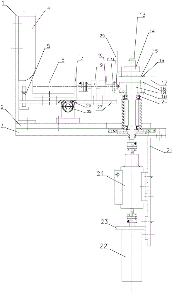
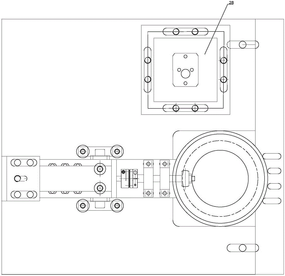
[0014] See attached figure 1 , a boundary slip test device with controllable slip-to-roll ratio, the test device includes four parts: friction pair kinematic system, loading system, microscope observation system and support system.

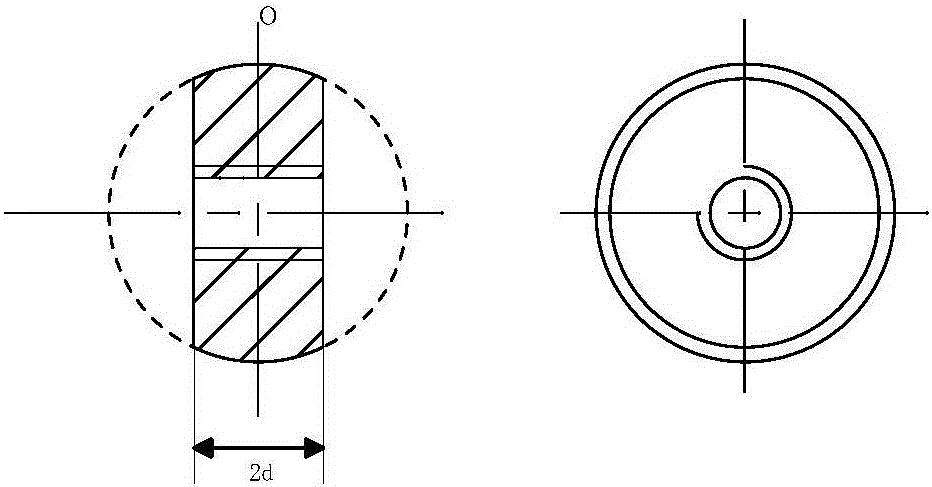
[0015] See attached figure 2 , the friction pair motion system is further divided into a first friction element motion control assembly and a second friction element motion control assembly. The motion control assembly of the first friction element includes: a first motor 6 , a shaft coupling, a ball bat 10 , a first friction element 11 and a first fixing nut 12 . The first friction element 11 is installed at one end of the ball bat 10, fixed and positioned by the first fixing nut 12; the first motor 6 is connected to the other end of the ball bat 10 through a coupling, thereby controlling the movement of the first friction...


PUM


Abstract

The invention belongs to the field of measurement of flow velocities of fluids and particularly relates to a boundary slip test device with the controllable slip ratio. The device comprises a first friction element (11), a second friction element (17), a loading system and a microscope (29), wherein the first friction element (11) and the second friction element (17) are driven by a first motor (6) and a second motor (22) respectively; the loading system adjusts a load between the first friction element (11) and the second friction element (17) by adjusting the pressing force between the first friction element (11) and the second friction element (17); the microscope (29) is used for observing the thickness of an oil film between contact positions of the first friction element (11) and the second friction element (17). With adoption of the device, the slip velocity can be measured according to the light-interference principle and the H-D empirical formula, and meanwhile, the device is applicable to boundary slip tests under various working conditions.

Description

technical field [0001] The invention belongs to the field of fluid flow velocity measurement, in particular to a boundary slip test device. Background technique [0002] Under the condition of high shear strain, the fluid is easy to slip on the solid surface, which leads to the weakening of the dynamic pressure of the fluid and the reduction of the thickness of the oil film. With the development of the current machinery towards high speed and heavy load, the shear strain rate in the mechanical pair can reach 106 ~ 107 s-1, and the resulting boundary slip will directly lead to a sharp decrease in the thickness of the oil film. When the two surfaces are in direct contact, As a result, the surface is worn and the normal operation of the machine is affected. Therefore, boundary slip has become an important factor restricting the development of the machine. In fact, different operating speeds, different working loads, and different slip-roll ratios will all have an important imp...

Claims


Application Information

Patent Timeline
IPC IPC(8): G01N13/00
CPCG01N13/00
Inventor 魏超赵欣苑士华李艳齐
Owner BEIJING INSTITUTE OF TECHNOLOGYGY
Learn More