
Visual angle control element and manufacturing method thereof, and liquid crystal display device

A technology of viewing angle control and components, which is applied in the field of liquid crystal displays, can solve the problems of complex backlight system, inability to switch, complex design, etc., and achieve the effect of simple process and excellent effect

Inactive Publication Date: 2016-10-12
SHENZHEN CHINA STAR OPTOELECTRONICS TECH CO LTD
View PDF4 Cites 38 Cited by
  • Summary
  • Abstract
  • Description
  • Claims
  • Application Information

AI Technical Summary

Problems solved by technology

The first method: the viewing angle cannot be switched, that is, the wide viewing angle and the narrow viewing angle cannot be switched at will after the blocking film is attached; the second method requires a complex backlight system and high cost; the third method requires additional control electrodes, design Complicated and prone to loss of aperture ratio

Method used


Image

  • Visual angle control element and manufacturing method thereof, and liquid crystal display device
  • Visual angle control element and manufacturing method thereof, and liquid crystal display device
  • Visual angle control element and manufacturing method thereof, and liquid crystal display device

Examples


Embodiment Construction

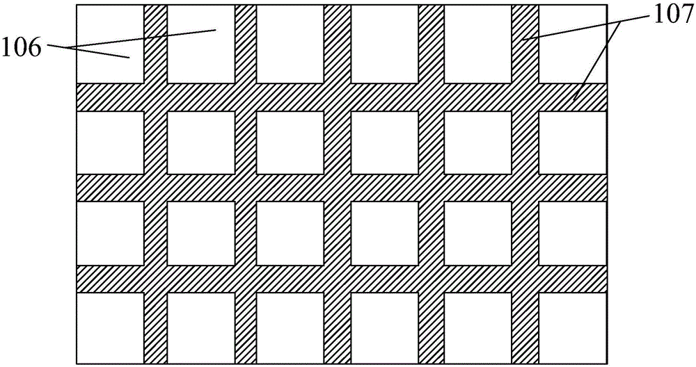
[0035] see figure 1 , figure 2 and image 3 , figure 1 It is a structural schematic diagram of a preferred embodiment of the viewing angle control element of the present invention, figure 2 It is a top view of the patterned transparent photoresist layer in this preferred embodiment, image 3 is a cross-sectional view of the patterned transparent photoresist layer in the preferred embodiment. The viewing angle control element 100 of this preferred embodiment mainly includes a first transparent substrate 101, a first transparent electrode layer 102, a patterned transparent photoresist layer 103, a second transparent electrode layer 104, and a second transparent electrode layer stacked sequentially from bottom to top. Transparent substrate 105; the patterned transparent photoresist layer 103 includes a plurality of rectangular transparent photoresists 106 arranged in a matrix, and the rectangular transparent photoresists 106 are separated by strip-shaped gaps 107 distribute...


PUM


Abstract

The invention relates to a visual angle control element and a manufacturing method thereof, and a liquid crystal display device. The visual angle control element comprises a first transparent substrate, a first transparent electrode layer, a patterned transparent photoresistor layer, a second transparent electrode layer and a second transparent substrate which are sequentially laminated from bottom to top, wherein the patterned transparent photoresistor layer comprises a plurality of rectangular transparent photoresistors which are arranged in a matrix mode; the rectangular transparent photoresistors are separated by strip gaps which are distributed longitudinally and transversely; and the strip gaps are filled with polymer dispersed liquid crystals. When in the narrow visual angle mode, the first transparent electrode layer and the second transparent electrode layer are not powered up, and the polymer dispersed liquid crystals are in the scattering state; and when in the wide visual angle mode, the first transparent electrode layer and the second transparent electrode layer are powered up, and the polymer dispersed liquid crystals are in the transparent state. The visual angle control element is simple in technique, has favorable effects, and can switch the visual angle freely. The visual angle control element does not need additional backlight or pixel design.

Description

technical field [0001] The invention relates to the field of liquid crystal displays, in particular to a viewing angle control element, a manufacturing method, and a liquid crystal display device. Background technique [0002] With the development of science and technology and the improvement of people's quality of life, liquid crystal display devices have been seen everywhere in life, and people's requirements for liquid crystal display devices are getting higher and higher, and they are beginning to pursue large display screens, fast response speeds and higher resolution. [0003] At present, liquid crystal displays are gradually developing towards wide viewing angles. For example, portable electronic display devices with wide viewing angles such as mobile terminals, flat panel displays, and notebook computers. The design of wide viewing angles allows users to see complete and undistorted picture. However, when it comes to the user's personal privacy and important inform...

Claims


Application Information

Patent Timeline
Patent Type & Authority Applications(China)
IPC IPC(8): G02F1/1335G02F1/1334G02F1/1333
CPCG02F1/133512G02F1/1333G02F1/1334
Inventor 韦宏权
Owner SHENZHEN CHINA STAR OPTOELECTRONICS TECH CO LTD
Learn More