Array substrate, display panel and display device
An array substrate and substrate technology, applied in nonlinear optics, instruments, optics, etc., can solve the problem of short circuit between the common electrode and the data line, and achieve the effect of reducing the probability of short circuit and reducing the area
- Summary
- Abstract
- Description
- Claims
- Application Information
AI Technical Summary
Problems solved by technology
Method used
Image

Examples
Embodiment 1
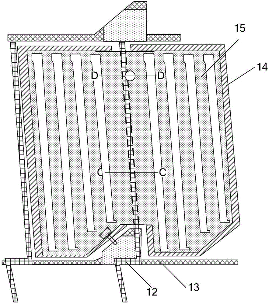
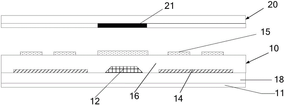
[0032] combine Figure 2a and 2b As shown, Embodiment 1 of the present invention provides an array substrate 10, including a substrate 11, data lines 12 and gate lines 13 formed on the substrate 11, and the data lines 12 and gate lines 13 intersect to form pixel regions. Specifically, a gate insulating layer 18 is formed above the gate line 13 , and the data line 12 is formed on the gate insulating layer 18 .
[0033] The array substrate 10 further includes a common electrode 15 and a connection electrode 17 formed on the substrate 11 , the common electrode 15 is located in the pixel area and does not cover the area corresponding to the data line 12 . The connection electrode 17 is connected to the common electrode 15 in adjacent pixel regions, and the projection of the connection electrode 17 on the substrate 11 intersects and does not completely overlap with the projection of the data line 12 on the substrate 11 .
[0034] Such as Figure 2b Shown, provided for embodiment...
Embodiment 2
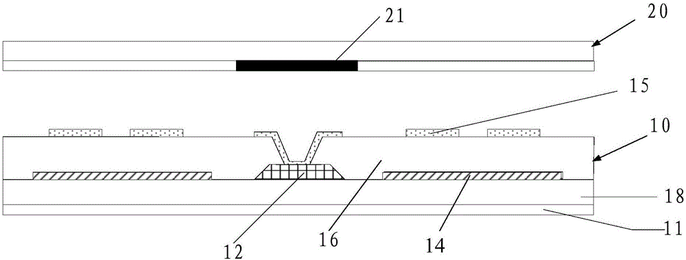
[0045] Embodiment 2 of the present invention provides an array substrate 10. The difference between Embodiment 2 and Embodiment 1 is that the relative positions of the common electrode 15, the pixel electrode 14 and the first protective layer 16 are different, and Embodiment 2 increases The second protective layer 19 is added. In Embodiment 1, the pixel electrode 14 and the data line 12 are arranged in the same layer, and the common electrode 15 is formed on the first protection layer 16 . However, in Embodiment 2, both the pixel electrode 14 and the common electrode 15 are arranged in different layers from the data line 12, the pixel electrode 14 is formed on the first protection layer 16, and the second protection layer is formed on the data line 12, The common electrode 15 is disposed on the second protection layer 19 . Other structures of the array substrate in Embodiment 2 are the same as those in Embodiment 1, and will not be repeated here.
[0046] Specifically, such ...
Embodiment 3
[0049] Embodiment 3 of the present invention also provides a display panel. The display panel includes the array substrate 10 as described above. Further, the display panel may also include a color filter substrate 20 on which a black matrix is arranged. twenty one.
[0050] By removing the common electrode above the data line, the common electrode is only located in the pixel area, and the common electrode of the adjacent pixel area is connected through the connecting electrode, and the projection of the connecting electrode on the substrate does not completely cover the area corresponding to the data line, reducing data. The area of the electrode above the line, that is, a relatively small connecting electrode is provided to connect to the common electrode of the adjacent pixel area, thereby reducing the probability of short circuit between the common electrode and the data line.
PUM
 Abstract
Description
Claims
Application Information
 - R&D
- Intellectual Property
- Life Sciences
- Materials
- Tech Scout
- Unparalleled Data Quality
- Higher Quality Content
- 60% Fewer Hallucinations
Browse by: Latest US Patents, China's latest patents, Technical Efficacy Thesaurus, Application Domain, Technology Topic, Popular Technical Reports.
© 2025 PatSnap. All rights reserved.Legal|Privacy policy|Modern Slavery Act Transparency Statement|Sitemap|About US| Contact US: help@patsnap.com