Lithium ion secondary battery and method for manufacturing the same
A technology of secondary battery and manufacturing method, which is applied in secondary battery, electrolyte storage battery manufacturing, battery pack components and other directions, can solve problems such as diaphragm size deviation, and achieve the effect of suppressing deviation
- Summary
- Abstract
- Description
- Claims
- Application Information
AI Technical Summary
Problems solved by technology
Method used
Image
Examples
Embodiment 1
[0129] The PP porous material of Example 1 was irradiated (ie, crosslinked) with a predetermined irradiation dose of electron beams.
[0130] The separator of Example 1 is a crosslinked separator obtained by cutting the crosslinked PP porous material with a hot knife at 200°C.
[0131] In Example 1, the heat shrinkage rate of the sample 1 after being left to stand in the atmosphere of 150 degreeC for 1 hour was 1%, and the variation of the dimension of the cut surface of the sample 2 was 0.02 mm.
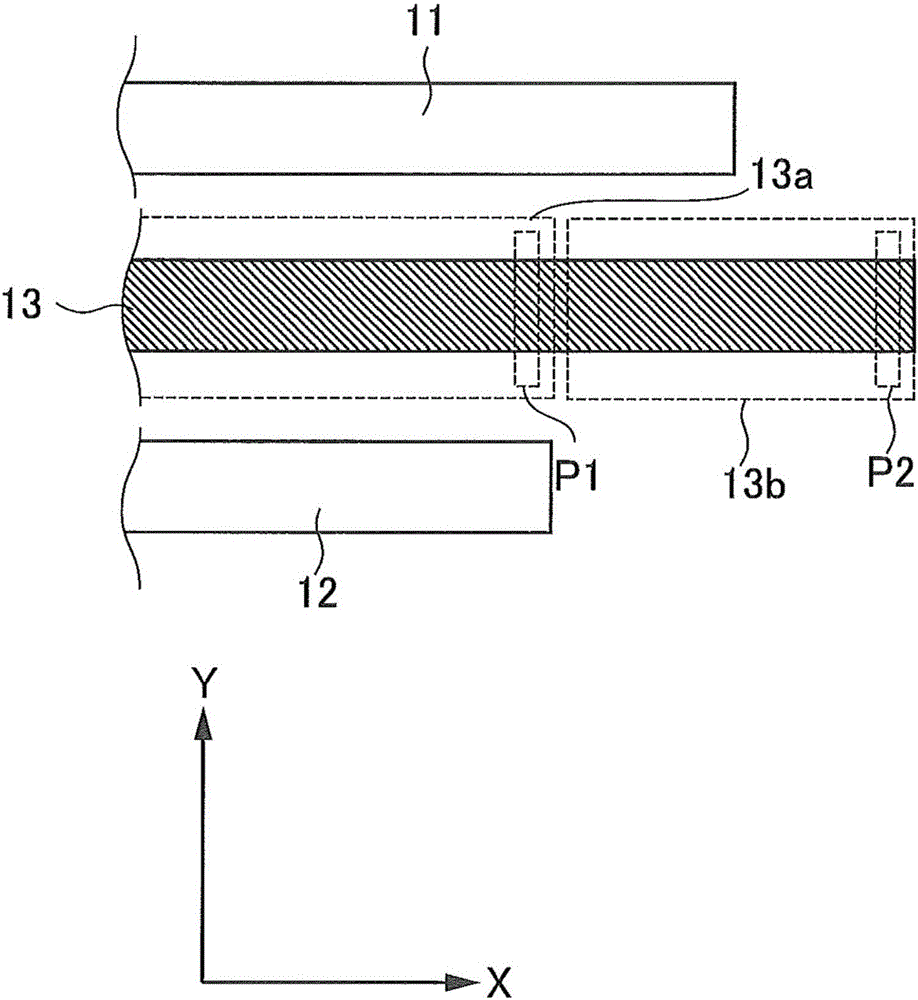
[0132] In addition, in Example 1, the region located 2 mm from the cut surface of sample 2 (for example, image 3 The porosity of the area P1) is about 50%, and it is located in the area 0.1 mm away from the cut surface of the sample 2 (for example image 3 The porosity of the region P2) is about 0%.
Embodiment 2
[0134] The PP porous material of Example 2 was irradiated with electron beams at a lower dose than that of Example 1 (that is, crosslinked).
[0135] The separator of Example 2 is a crosslinked separator obtained by cutting the crosslinked PP porous material with a hot knife at 200°C.
[0136] In Example 2, the heat shrinkage rate of the sample 1 after being left in the atmosphere of 150 degreeC for 1 hour was 3%, and the variation of the dimension of the cut surface of the sample 2 was 0.05 mm.
[0137] In addition, in Example 2, the area located 2 mm from the cut surface of the sample 2 (for example, image 3 The porosity of the area P1) is about 50%, and it is located in the area 0.1 mm away from the cut surface of the sample 2 (for example image 3 The porosity of the region P2) is about 0%.
[0138] Compared with Example 1, in Example 2, the thermal shrinkage rate of Sample 1 and the dimension of the cut surface of Sample 2 are more varied.
Embodiment 3
[0140] The PP porous material of Example 3 was irradiated with electron beams at a lower dose than that of Example 2 (that is, crosslinked).
[0141] The separator of Example 3 is a crosslinked separator obtained by cutting the crosslinked PP porous material with a hot knife at 200°C.
[0142] In Example 3, the heat shrinkage rate of the sample 1 after being left to stand in the atmosphere of 150 degreeC for 1 hour was 10%, and the variation of the dimension of the cut surface of the sample 2 was 0.08 mm.
[0143] In addition, in Example 3, the area located 2 mm from the cut surface of sample 2 (for example, image 3 The porosity of the area P1) is about 50%, and it is located in the area 0.1 mm away from the cut surface of the sample 2 (for example image 3 The porosity of the region P2) is about 0%.
[0144] Compared with Example 1 and Example 2, in Example 3, the thermal shrinkage rate of Sample 1 and the dimension of the cut surface of Sample 2 are more varied.
[0145]...
PUM
 Abstract
Description
Claims
Application Information
 - R&D
- Intellectual Property
- Life Sciences
- Materials
- Tech Scout
- Unparalleled Data Quality
- Higher Quality Content
- 60% Fewer Hallucinations
Browse by: Latest US Patents, China's latest patents, Technical Efficacy Thesaurus, Application Domain, Technology Topic, Popular Technical Reports.
© 2025 PatSnap. All rights reserved.Legal|Privacy policy|Modern Slavery Act Transparency Statement|Sitemap|About US| Contact US: help@patsnap.com


