Antenna capable of reducing equipment SAR value

An antenna and equipment technology, applied in the field of antennas that can reduce the SAR value of equipment, can solve the problems of reducing SAR value, reducing antenna performance, increasing antenna area, etc., to achieve the effect of reducing SAR value, optimizing antenna performance, and simplifying antenna design

Inactive Publication Date: 2016-10-12
SHENZHEN SUNWAY COMM
View PDF6 Cites 6 Cited by
  • Summary
  • Abstract
  • Description
  • Claims
  • Application Information

AI Technical Summary

Problems solved by technology

At present, the main ways to reduce the SAR value of the antenna include the following methods: 1. Through the distribution of components around the antenna, the current distribution on the main board in the antenna area is changed, thereby changing the peak radiation of the antenna; but this method is complicated to debug and difficult to implement
2. Through the distance sensor, when the sensor senses that the distance between the human body and the device is close, it will reduce the transmission power of the antenna transceiver to achieve the purpose of reducing the SAR value; this method will reduce the performance of the antenna, usually the transmission power is reduced by 1dB, The SAR value is reduced by 0.3W / Kg, and the reduction in transmission power will lead to a decrease in the performance of the antenna. If the transmission power is low to a certain extent, the device will even be unable to communicate.
3. Use two or more antenna units to design an antenna with reconfigurable pattern, and adjust the SAR value of a certain area through beam scanning. This method increases the area of ​​the antenna area, and the additional antenna will also improve manufacturing. cost

Method used


Image

  • Antenna capable of reducing equipment SAR value
  • Antenna capable of reducing equipment SAR value
  • Antenna capable of reducing equipment SAR value

Examples


Embodiment Construction

[0016] In order to make the object, technical solution and advantages of the present invention clearer, the present invention will be further described in detail below in conjunction with the accompanying drawings and embodiments. It should be understood that the specific embodiments described here are only used to explain the present invention, not to limit the present invention.

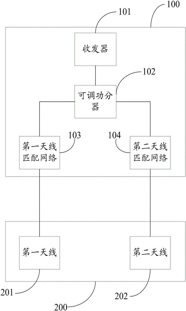
[0017] Aiming at the problems of high debugging complexity, difficulty in implementation, reduction in transmission power will lead to performance degradation of the antenna, and additional antennas will increase manufacturing costs in the current method of reducing the SAR value of the antenna, the present invention proposes a method of adjusting through the power division network to realize The antenna pattern reconstruction, through the adjustment of the antenna radiation direction, can effectively reduce the SAR value of the antenna.

[0018] see figure 1 as shown, figure 1 It is a schematic ...


PUM


Abstract

The invention provides an antenna capable of reducing an equipment SAR value. The antenna comprises a main circuit board and an antenna circuit board, wherein an adjustable power divider, and a first antenna matching network and a second antenna matching network respectively connected with the adjustable power divider are arranged on the main circuit board, a first antenna and a second antenna are respectively printed on the front and back sides of the antenna circuit board, the first antenna is connected with the first antenna matching network, and the second antenna is connected with the second antenna matching network. Antennas are printed on the front and back sides of an antenna circuit board, and no extra antenna units or devices added on the surrounding of an antenna are needed, thereby simplifying antenna design and saving space. Reconstruction of an antenna directional diagram can be realized through adjusting of a power division network. The SAR value can be effectively reduced through further adjusting antenna radiation direction. Commissioning is flexible, and the performance of an antenna can be optimized by fine tuning antenna wiring and matching elements.

Description

technical field [0001] The invention relates to an antenna, in particular to an antenna capable of reducing the SAR value of a device. Background technique [0002] Electromagnetic radiation specific absorption ratio (Specific Absorption Ratio, SAR) refers to the electromagnetic radiation energy absorbed by a unit mass of material per unit time, and is an important parameter to measure the impact of radiation from mobile devices such as mobile phones on the human body. There are strict requirements on the SAR value of mobile devices when they are authenticated into the network. At present, there are two international SAR value standards, one is the European standard 2w / kg, and the other is the American standard 1.6w / kg. The specific meanings are It means that with 6 minutes as the timing, the electromagnetic radiation energy absorbed by each kilogram of human tissue shall not exceed 2 watts or 1.6 watts. [0003] For a mobile device, it needs to ensure that the SAR value of...

Claims


Application Information

Patent Timeline
Patent Type & Authority Applications(China)
IPC IPC(8): H01Q1/24H01Q1/38H01Q3/26
CPCH01Q1/245H01Q1/38H01Q3/26
Inventor 刘健毕晔海周仲蓉
Owner SHENZHEN SUNWAY COMM
Why Eureka
Try Eureka