High voltage fittings for electric power circuit
A power line, high-voltage technology, applied in circuits, transformers, inductors, etc., can solve the problems of poor firmness and easy loosening, and achieve the effects of labor-saving operation, reasonable center of gravity distribution, and good anti-loosening effect.
- Summary
- Abstract
- Description
- Claims
- Application Information
AI Technical Summary
Problems solved by technology
Method used
Image

Examples
Embodiment 1)
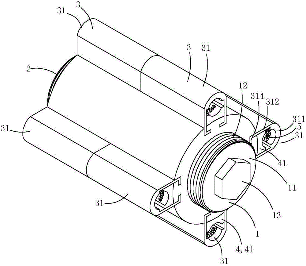
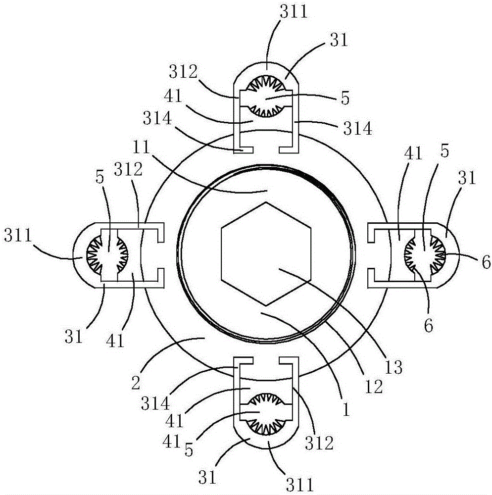
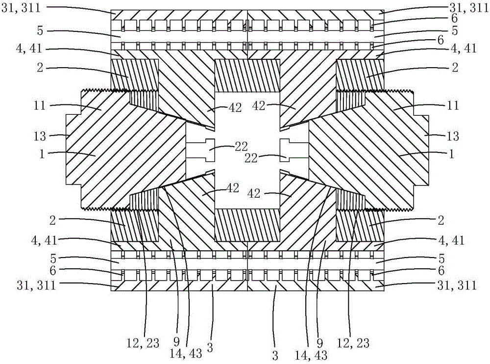
[0019] This embodiment is a kind of high-voltage fittings for power lines, see Figure 1 to Figure 5 As shown, it includes a core tube 2 , two jacking bolts 1 , two sets of crimping assemblies 3 and two sets of pressing claw assemblies 9 .
[0020] Two groups of guide holes are arranged on the tube wall of the core tube, and the two groups of guide holes are arranged side by side along the axial direction of the core tube; each group of guide holes includes four radial guide slide holes 22, and the four radial guide slide holes The circumferential direction of the tube is evenly distributed on the tube wall of the core tube; each radial guiding slide hole runs through the tube wall of the core tube along the radial direction of the core tube; the cross-sectional shape of each radial guiding sliding hole is I-shaped. There are two internally threaded areas 23 in the lumen of the core tube.
[0021] Each set of crimping components 3 includes four crimping parts 31; each crimpin...
Embodiment 2)
[0036] This embodiment is basically the same as Embodiment 1, the difference is: see Figure 6 to Figure 7 As shown, at least one crimping member 31 is provided with a mounting screw hole 315 penetrating through the wall of the pressing plate portion 311 in the radial direction of the core tube; a temperature sensing device 8 is fixedly installed in the mounting screw hole.
[0037] The temperature sensing device 8 includes a metal housing 81 made of metal material with a containing groove 811, a temperature sensor 82 arranged in the containing groove, and a spring 83 for crimping the temperature sensor on the bottom wall of the containing groove , The screw tube plug 84 that is used for limit spring.
[0038] One end 812 of the metal shell close to the central axis of the core tube is provided with a heat conduction boss 813 used as a puncture, and one end 814 of the metal shell away from the central axis of the core tube is provided with an inner hexagonal screw groove 815; ...
Embodiment 3)
[0046] This embodiment is basically the same as Embodiment 1, the difference is: see Figure 8 As shown, this embodiment also includes a current transformer 7; the current transformer includes an annular induction body 71 and an intelligent control module 72; in this embodiment, the intelligent control module 72 is made into a ring with the same size cavity as the annular induction body The ring-shaped inductive sensing body and the intelligent control module are arranged side by side to form a ring shape, and the current transformer is sleeved and fixed on the outer wall of the pressing plate part as a whole, that is, the crimping assembly is located in the cavity of the current transformer as a whole. In practice, the current transformer can also be fixedly arranged on the tube wall of the core tube, as long as all the clamping holes are located in the cavity of the ring-shaped induction body, that is, it is only necessary to make the cable pass through the hole of the ring-s...
PUM
 Abstract
Description
Claims
Application Information
 - R&D
- Intellectual Property
- Life Sciences
- Materials
- Tech Scout
- Unparalleled Data Quality
- Higher Quality Content
- 60% Fewer Hallucinations
Browse by: Latest US Patents, China's latest patents, Technical Efficacy Thesaurus, Application Domain, Technology Topic, Popular Technical Reports.
© 2025 PatSnap. All rights reserved.Legal|Privacy policy|Modern Slavery Act Transparency Statement|Sitemap|About US| Contact US: help@patsnap.com