
Control device and method for three-phase unbalance and reactive power compensation

A control device and three-phase technology, applied in reactive power compensation, reactive power adjustment/elimination/compensation, circuit devices, etc., can solve problems such as reactive power and current imbalance, limited adjustment ability, and compensation accuracy that cannot meet the requirements , to achieve the effects of ABC three-phase current balance, precise dynamic compensation, and reactive power compensation

Active Publication Date: 2016-10-12
SHENZHEN TIEON ENERGY TECH
View PDF3 Cites 13 Cited by
  • Summary
  • Abstract
  • Description
  • Claims
  • Application Information

AI Technical Summary

Problems solved by technology

[0003] However, the capacitance and inductance switching devices involved in the traditional technology cannot quickly compensate for reactive power, the compensation accuracy cannot be guaranteed, and the imbalance of three-phase active power (current) cannot be effectively adjusted; the imbalance degree still exceeds 5% after current imbalance adjustment , cannot meet the compensation accuracy requirements, and the adjustment ability is limited
[0004] SVG (Static Var Generator) is mainly used to compensate reactive power. It is mostly used in three-phase three-wire high-voltage systems without a neutral wire. Because it does not have a neutral wire, it cannot compensate zero-sequence current and cannot adjust the imbalance of reactive power.
APF (active filter) can only compensate the harmonics of the current, but cannot compensate the zero-sequence current, and has limited ability to compensate for the imbalance of three-phase active power
[0005] In addition, schemes such as three-phase four-leg can compensate zero-sequence current, but the efficiency is low and the cost is increased
That is to say, the shortcomings of the existing technology mainly include: it is mostly used in the three-phase three-wire system, and the zero line current of the three-phase four-wire system cannot be suppressed; the topology is complex, and the use of three-phase four-arm solutions increases the cost; The switching devices are used at the same time, and the current contains low-order harmonics such as 3, 5, 7, 9 and 11, which cause resonance; the reactive power and current imbalance cannot be compensated by one device, the time required for compensation is long, and the compensation accuracy cannot meet the requirements. Require

Method used


Image

  • Control device and method for three-phase unbalance and reactive power compensation
  • Control device and method for three-phase unbalance and reactive power compensation

Examples


Embodiment 1

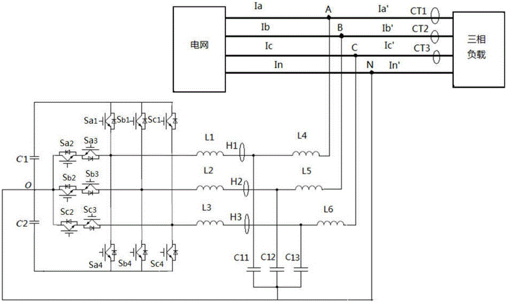
[0026] Such as figure 1 As shown, this example provides a control device for three-phase unbalance and reactive power compensation, including: a three-phase switch control circuit, a filter module and a current sampling module, and the three-phase switch control circuit is connected through the filter module To the power grid, the three-phase switch control circuit and the filter module are connected to the A, B, C and N lines of the three-phase load, and the three-phase output current of the three-phase load is respectively connected to the filter through the current sampling module module.

[0027] The control device described in this example outputs three-phase inductive current, each negative-sequence and zero-sequence component separated by the three-phase inductive current, each negative-sequence and zero-sequence component separated by the three-phase inductive current and the three-phase load The negative sequence and zero sequence components separated by the three-ph...

Embodiment 2

[0038]This example also provides a control method for three-phase unbalance and reactive power compensation, which adopts the control device for three-phase unbalance and reactive power compensation as described in Embodiment 1, and includes the following steps:

[0039] Step S1, calculating a given first zero-sequence component;

[0040] Step S2, extracting the second positive-sequence component filter value, the third positive-sequence component filter value, the second negative-sequence component filter value and the third negative-sequence component filter value of the three-phase output current, and simultaneously extracting the first three-phase inductor current The instantaneous value of the second positive sequence component, the third instantaneous value of the positive sequence component, the second instantaneous value of the negative sequence component and the third instantaneous value of the negative sequence component;

[0041] Step S3, giving a filtered value to ...


PUM


Abstract

The invention provides a control device and a method for three-phase unbalance and reactive power compensation. The control device comprises a three-phase switch control circuit, a filter module and a current sampling module, wherein the three-phase switch control circuit is connected to the power grid via the filter module; the three-phase switch control circuit and the filter module are connected onto A, B, C of a three-phase load and an N wire; and the three-phase output current of the three-phase load is respectively connected onto the filter module via the current sampling module. The three-phase output current is controlled through a loop of the three-phase switch control circuit, the sizes of each negative-sequence component instantaneous value and each zero-sequence component instantaneous value separated from the outputted three-phase inductor current are the same as those separated by the A, B, C three-phase output current at the three-phase load side but the directions are opposite, A, B, C three phases of current of the power grid are balanced, and the purposes of quick response, accurate three-phase unbalanced current dynamic compensation and reactive power compensation are realized.

Description

technical field [0001] The invention relates to a three-phase control device, in particular to a control device for three-phase unbalance and reactive power compensation, and to a control method using the control device for three-phase unbalance and reactive power compensation. Background technique [0002] A large number of three-phase four-wire wiring methods are used in urban and rural distribution networks. With the continuous improvement of people's living standards, the power load structure in the power system has undergone major changes. The types of residential electrical equipment increase, and the power consumption increases accordingly. There are many single-phase and three-phase loads, which makes the three-phase unbalance problem in the distribution network field more and more prominent, which leads to increasingly serious power quality problems in the power grid. In some areas, the current unbalance degree of the low-voltage side of the station substation excee...

Claims


Application Information

Patent Timeline
Patent Type & Authority Applications(China)
IPC IPC(8): H02J3/26H02J3/18
CPCH02J3/1842H02J3/26Y02E40/30Y02E40/50
Inventor 迟屹楠
Owner SHENZHEN TIEON ENERGY TECH
Learn More