
Wireless power transmission device

A technology of wireless power transmission and power input, applied in circuit devices, electrical components, etc., can solve problems such as low transmission efficiency and low radiation, and achieve the effect of eliminating dead zones and improving efficiency

Active Publication Date: 2016-10-12
江苏卓燃知识产权运营有限公司
View PDF4 Cites 5 Cited by
  • Summary
  • Abstract
  • Description
  • Claims
  • Application Information

AI Technical Summary

Problems solved by technology

[0004] So far, the application of wireless power transmission still faces the following problems: long-distance, regional, transmission efficiency, low radiation, etc., in the prior art, it is single-transmitter, single-receiver, one-to-one, point-to-point, short-distance Correspondingly, the coils used as the transmitting end and the receiving end are usually a two-dimensional structure such as a rectangle or a circle. This two-dimensional coil has strong directionality and can only move in a specific direction. It has the greatest transmission efficiency. Once the receiving coil deviates from a specific direction, the energy received by the receiving coil will become smaller and smaller, and even enter the dead zone of energy transmission. It is impossible to truly realize multiple directions in three-dimensional space. power transfer to the load

Method used


Image

  • Wireless power transmission device
  • Wireless power transmission device
  • Wireless power transmission device

Examples


Embodiment Construction

[0027] The present invention will be further described below in conjunction with accompanying drawing:

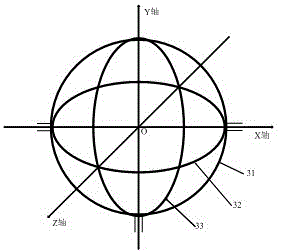
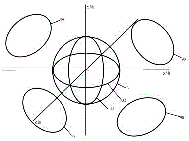
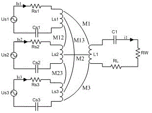
[0028] Such as Figure 1-Figure 6 The shown wireless power transmission device includes a transmitting end and a receiving end, and the rotating mechanism of the transmitting end includes a base 10, a turntable 20 arranged on the base, and a first support body 21 and a second support body 22 arranged on the turntable 20 . The base 10 is also provided with balls 11, through which the turntable 20 can rotate flexibly and smoothly. The number of transmitting coils 30 can be three or more, wherein at least one transmitting coil is required on each plane of the three-dimensional coordinate system, and the center points of all transmitting coils are required to be on the same center point, and certain errors are allowed , in this embodiment, three coils are taken as an example, which are respectively the transmitting coil 31, the transmitting coil 32 and the transmitting coil 3...


PUM


Abstract

The invention relates to a wireless power transmission device, which comprises a transmitting terminal and a receiving terminal, wherein the transmitting terminal comprises at least three concentric transmitting coils and a rotating mechanism for driving the transmitting coils to transversely rotate; the at least three concentric transmitting coils are located in XOY, XOZ and YOZ planes of a three-dimensional coordinate system; the transmitting terminal further comprises a power supply input module, a main control module and a signal receiving module; the power supply input module is arranged on the rotating mechanism; the main control module is used for controlling the transmitting terminal to rotate and to process a signal; an output end of the power supply input end is connected with the input ends of the transmitting coils; the main control module and the power supply input module are interactive connection; and the output end of the signal receiving module is connected with the input end of the main control module. Wireless power transmission can be carried out in a random direction within a three-dimensional space through the transmitting coils with the transmitting terminal structures; and wireless power transmission can also be simultaneously carried out on a plurality of loads which are placed in different directions in the area.

Description

technical field [0001] The invention relates to the field of wireless power transmission, in particular to a wireless power transmission device. Background technique [0002] Wireless Power Transfer (WPT) is a technology that uses electromagnetic fields, electromagnetic waves, lasers, and ultrasonic waves for energy transfer. So far, the methods that can realize wireless energy transmission mainly include microwave, laser, magnetic coupling resonance, electric field coupling, electromagnetic induction, etc., which can realize energy transmission from low power to high power, long distance to short distance, and different power requirements. . [0003] Wireless power transmission technology has broad application prospects in various mobile electromechanical equipment, medical equipment, electronic product chargers and other fields. For example, urban light rail, electric locomotives, industrial and mining vehicles, etc., the general power supply method is sliding friction, ...

Claims


Application Information

Patent Timeline
Patent Type & Authority Applications(China)
IPC IPC(8): H02J50/10
Inventor 郭润峰高小朋
Owner 江苏卓燃知识产权运营有限公司
Learn More