Balance weights for motors, motors for compressors and compressors

A technology of balance weights and compressors, which is applied in the direction of machines/engines, electromechanical devices, electrical components, etc., which can solve the problems of reducing compressor efficiency, increasing rotor rotation resistance, and breaking oil droplets, so as to reduce atomization of oil droplets, The effect of reducing the amount of oil spit out and the amount of oil spit out is small

Active Publication Date: 2018-11-06
ANHUI MEIZHI PRECISION MFG
View PDF5 Cites 0 Cited by
  • Summary
  • Abstract
  • Description
  • Claims
  • Application Information

AI Technical Summary

Problems solved by technology

However, when the compressor is running, on the one hand, the refrigerant airflow directly hits the windward side of the balance weight, resulting in a strong stagnation effect and a significant resistance torque, which increases the rotational resistance of the rotor and reduces the efficiency of the compressor.
On the other hand, the refrigerant air flow carries a large number of oil droplets. During the rotation of the balance weight, a large number of oil droplets will directly hit the windward side of the balance weight and break up, which will significantly increase the number of tiny oil droplets in the compressor. , resulting in an increase in the oil output of the compressor

Method used


Image

  • Balance weights for motors, motors for compressors and compressors
  • Balance weights for motors, motors for compressors and compressors
  • Balance weights for motors, motors for compressors and compressors

Examples


Embodiment 1

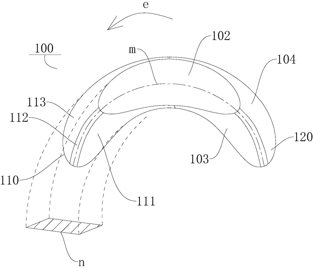
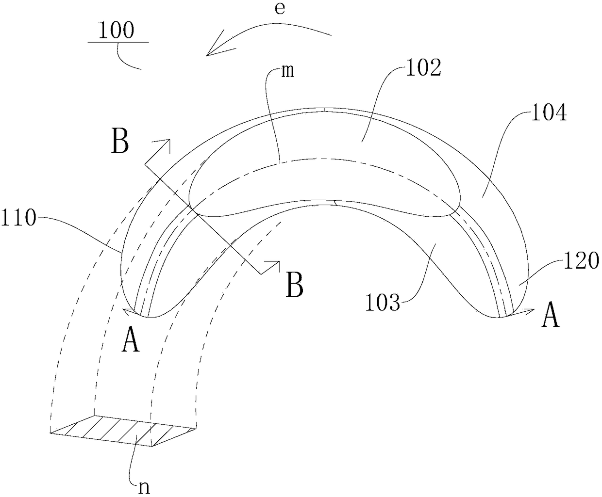
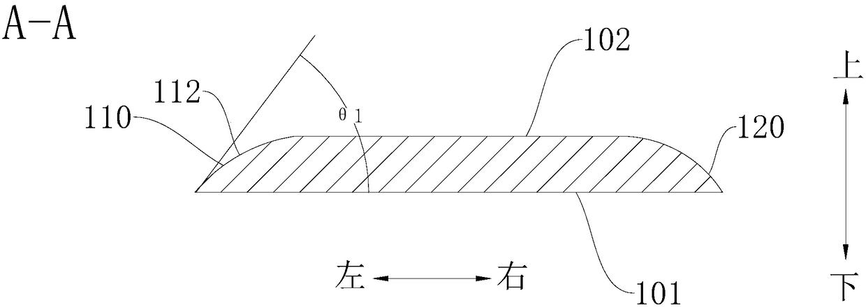
[0049] Such as Figure 1-Figure 7 As shown, in this embodiment, the balance weight 100 has a first end surface 101 and a second end surface 102 oppositely arranged, as Figure 5 As shown, the lower end surface of the balance weight 100 is the first end surface 101 , and the upper end surface of the balance weight 100 is the second end surface 102 . The first end surface 101 is suitable for connecting with the rotor of the motor, and the two ends of the balance weight 100 in the extension direction are a windward end 110 and a leeward end 120 respectively. Such as figure 1 As shown, the arrow e is the direction in which the rotor rotates. The rotor can drive the balance weight 100 to rotate in the direction indicated by the arrow e. The leeward end 120 is located upstream of the rotor's rotational direction, and the windward end 110 is located downstream of the rotor's rotational direction. The windward end portion 110 is connected between the first end surface 101 and the se...

Embodiment 2

[0056] Such as Figure 8 As shown, the difference from Embodiment 1 is that in this embodiment, the intersection line of the inner side flow distribution surface 111 and the outer side flow distribution surface 113 is configured as the middle windward portion 112 . Thus, the windward area of ​​the balance weight 100 can be further reduced, thereby reducing the windward resistance, preventing the oil droplets carried in the refrigerant airflow from colliding with the wall of the balance weight 100 vertically, reducing the atomization of the oil droplets caused by the rotation of the balance weight 100, The oil discharge volume of the compressor is reduced, so that the compressor has the advantages of high energy efficiency and small oil discharge volume.

[0057] The motor of the compressor according to the embodiment of the present invention includes: the rotor and the balance weight 100 of the motor described in the above embodiments. Specifically, the balance weight 100 is ...


PUM


Abstract

The invention discloses a balance weight of a motor, a motor of a compressor and a compressor. Wherein, the balance weight has a first end surface and a second end surface oppositely arranged, the first end surface is suitable for connecting with the rotor of the motor, and the two ends in the extension direction of the balance weight are respectively a windward end and a leeward end, and the windward end is connected to Between the first end surface and the second end surface, in the direction from the first end surface to the second end surface, the windward end portion is inclined towards the leeward end portion. According to the balance weight of the motor of the present invention, by setting the windward end portion obliquely, on the one hand, the resistance of the fluid flowing around the windward end portion to the second end surface can be reduced; The oil droplets carried in the refrigerant airflow hit the wall of the balance weight vertically, reducing the atomization of the oil droplets caused by the rotation of the balance weight, and reducing the oil discharge volume of the compressor, so that the compressor has the advantages of high energy efficiency and small oil discharge volume.

Description

technical field [0001] The invention relates to the technical field of refrigeration equipment, in particular, to a balance weight of a motor, a motor of a compressor, and a compressor. Background technique [0002] The hermetic rotary compressor uses the eccentric rotation of the rotor to compress the refrigerant gas. Since the unbalanced moment generated by the eccentric rotation will cause the compressor to vibrate violently, it is necessary to install balance weights on the upper and lower parts of the motor rotor. However, when the compressor is running, on the one hand, the refrigerant airflow directly hits the windward side of the balance weight, resulting in a strong stagnation effect and a significant resistance torque, which increases the rotational resistance of the rotor and reduces the efficiency of the compressor. On the other hand, the refrigerant air flow carries a large number of oil droplets. During the rotation of the balance weight, a large number of oil ...

Claims


Application Information

Patent Timeline
Patent Type & Authority Patents(China)
IPC IPC(8): H02K7/04F04C23/02
CPCF04C23/02H02K7/04
Inventor 曹红军曹小军朱斌生
Owner ANHUI MEIZHI PRECISION MFG
Why Eureka
Try Eureka