Permanent magnet synchronous electric drive system

A technology of electric drive system and permanent magnet synchronization, which is applied in electric vehicles, single motor speed/torque control, collectors, etc., and can solve problems such as narrow speed range

Inactive Publication Date: 2016-10-12
HUNAN UNIV
View PDF4 Cites 10 Cited by
  • Summary
  • Abstract
  • Description
  • Claims
  • Application Information

AI Technical Summary

Problems solved by technology

The speed regulation range of the traditional drive system is narrow, and it is difficult to meet the performance requirements of providing high torque in the low speed area and outputting high power in the high speed area

Method used


Image

  • Permanent magnet synchronous electric drive system
  • Permanent magnet synchronous electric drive system

Examples


Embodiment Construction

[0027] The following will clearly and completely describe the technical solutions in the embodiments of the present invention with reference to the accompanying drawings in the embodiments of the present invention. Obviously, the described embodiments are only some, not all, embodiments of the present invention. Based on the embodiments of the present invention, all other embodiments obtained by persons of ordinary skill in the art without making creative efforts belong to the protection scope of the present invention.

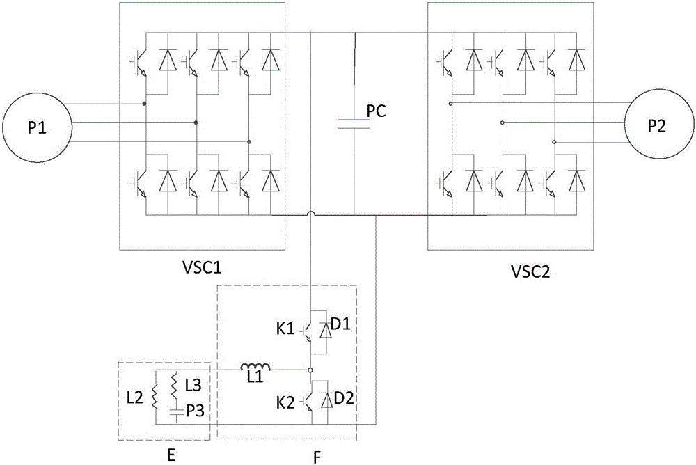
[0028] figure 1 It is a structural diagram of a permanent magnet synchronous electric drive system provided by an embodiment of the present invention;

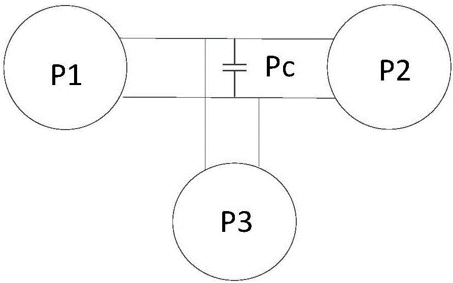
[0029] figure 2 It is an energy flow diagram of a permanent magnet synchronous electric drive system provided by an embodiment of the present invention.

[0030] like figure 1 and figure 2 A permanent magnet synchronous electric drive system shown includes: a permanent magnet synchronous generator P1 for...


PUM


Abstract

The invention provides a permanent magnet synchronous electric drive system. The permanent magnet synchronous electric drive system comprises a permanent magnet synchronous generator, a first conversion device, a second conversion, a permanent magnet synchronous motor, a first detector, a second detector and a controller, wherein the output end of the permanent magnet synchronous generator is connected to the input end of the first conversion device, the output end of the first conversion device is connected to the input end of the second conversion device, and the output end of the second conversion device is connected to the input end of the permanent magnet synchronous motor; the first detector and the second detector are connected to the controller respectively; the first detector is used for detecting direct-current bus voltage and sending the direct-current bus voltage to the controller, the second detector is used for detecting the operational state of load and sending the operation state of load to the controller, the controller is used for sending control signals to the first conversion device and the second conversion device according to the two signals, and the first conversion device and the second conversion device are used for carrying out conversion according to the two control signals so as to adjust output power of the permanent magnet synchronous generator and output power output to the permanent magnet synchronous motor. The permanent magnet synchronous electric drive system can realize unity power factor control.

Description

technical field [0001] The invention relates to the technical field of motors, in particular to a permanent magnet synchronous electric drive system. Background technique [0002] Traditional motor drive systems have limitations. First of all, the power density of the drive system is low, resulting in increased motor volume, weight and capacity of power devices. For a drive system with a larger power, simply adopting a larger-sized motor and a converter reduces the specific power and specific energy of the system. Large volume and low power density are the main problems of conventional drive systems. [0003] When the current motor drive system adopts uncontrolled rectification, the power factor is low and uncontrollable; when the motor brakes, it is easy to generate high feedback energy and pump voltage, and the traditional drive system relies on DC capacitors to absorb energy, making the system unreliable . Second, modern motor drive systems require high energy efficie...

Claims


Application Information

Patent Timeline
Patent Type & Authority Applications(China)
IPC IPC(8): H02M5/458H02P6/08H02J7/00
CPCH02J7/00H02J7/0068H02J2207/20H02M5/458H02P6/08
Inventor 高剑黄守道罗德荣樊鹏
Owner HUNAN UNIV
Why Eureka
Try Eureka