
High-performance self-test external reference time-base circuit and implementation method thereof

A time-based circuit and self-detection technology, applied in the direction of electrical components, automatic power control, etc., can solve the problems of inability to directly judge whether the external reference signal is input, high circuit cost, etc.

Active Publication Date: 2016-10-12
THE 41ST INST OF CHINA ELECTRONICS TECH GRP
View PDF7 Cites 2 Cited by
  • Summary
  • Abstract
  • Description
  • Claims
  • Application Information

AI Technical Summary

Problems solved by technology

[0009] First: In the external reference time base circuit, the upper computer can only switch between the external reference and internal reference signals by controlling the one-of-two switch. Even if it is switched to the external reference signal input state, it cannot directly judge whether the external reference signal is input.
[0010] Second: A high-performance constant temperature crystal oscillator and voltage-controlled oscillator are required in the entire circuit, and the cost of the circuit is relatively high
[0011] Third: In the reference source generation circuit, the upper computer cannot achieve the generation control of the reference source signal through simple control

Method used


Image

  • High-performance self-test external reference time-base circuit and implementation method thereof

Examples


Embodiment Construction

[0038] The present invention will be further described below in conjunction with the accompanying drawings and embodiments.

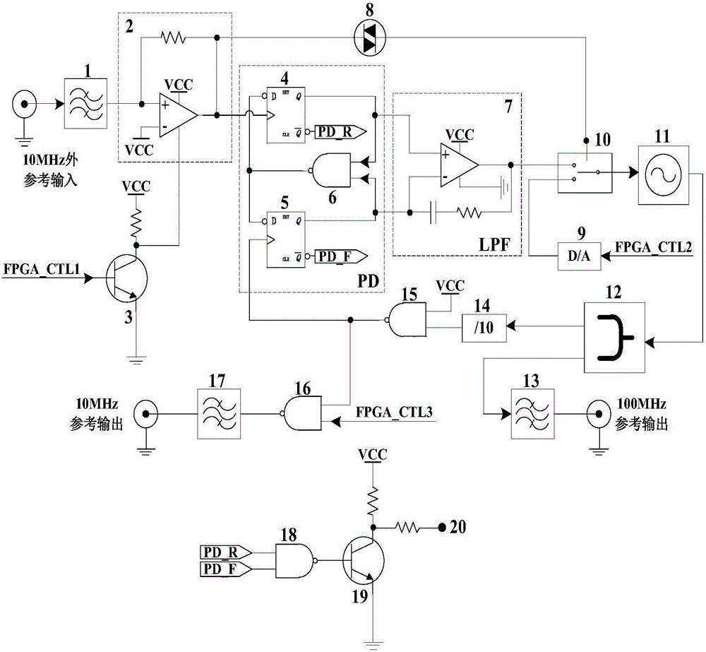
[0039] A high-performance self-detection external reference time base circuit, comprising: an external reference filter amplifier circuit connected in series, an external reference self-detection circuit, an external reference phase detection filter circuit, a switch 10 and a constant temperature crystal oscillator 11; The output terminal of the external reference self-detection circuit is connected to the selection control terminal of the one-two switch 10; the output terminal of the external reference phase detection filter circuit is connected to one of the input terminals of the one-two switch 10;

[0040] When the external reference signal is input, the external reference filter amplifying circuit filters and amplifies the external reference signal and divides it into two circuits, one of which is connected to the external reference phase detection ...


PUM


Abstract

The invention discloses a high-performance self-test external reference time-base circuit and an implementation method thereof. The high-performance self-test external reference time-base circuit comprises an external reference filtering and amplifying circuit, an external reference self-test circuit, an external reference phase discrimination filtering circuit, an one-out-of-two switch and a constant-temperature crystal oscillator, wherein an output end of the external reference self-test circuit is connected with a selection control end of the one-out-of-two switch; an output end of the external reference phase discrimination filtering circuit is connected with one input end of the one-out-of-two switch; when an external reference signal is input, the external reference filtering and amplifying circuit partitions the external reference signal into two paths after filtering and amplifying the external reference signal; one path of the external reference signal is connected with the external reference phase discrimination filtering circuit; the other path of the external reference signal is connected with the external reference self-test circuit; and the one-out-of-two switch is controlled to be switched to an output end of the external reference phase discrimination filtering circuit in order to perform loop phase locking on the external reference signal. The high-performance self-test external reference time-base circuit has the beneficial effects that a complete machine can decide whether to use the external reference signal not under the control of an FPGA (Field Programmable Gate Array) even when the external reference signal is input.

Description

technical field [0001] The invention relates to the technical field of measuring instrument circuits, in particular to a high-performance self-detection external reference time base circuit and a realization method thereof. Background technique [0002] In the use of various test instruments, the external reference time base circuit and the controllable reference source generating circuit are necessary circuits for the measuring instrument. Therefore, the intelligence and flexibility of the circuit have a great influence on the measurement accuracy and practicability of the measuring instrument. [0003] The current external reference time base circuit is mainly realized in the following ways: [0004] The traditional external reference time base circuit is generated in the following way: through the host computer to control a switch to select the internal reference clock or external reference clock for the whole machine, when the switch selects the internal reference clock...

Claims


Application Information

Patent Timeline
IPC IPC(8): H03L7/099
CPCH03L7/0992
Inventor 王李飞张宁
Owner THE 41ST INST OF CHINA ELECTRONICS TECH GRP
Learn More