
An on-orbit focusing method of a spaceborne visible light transmission camera for earth observation

An earth observation and visible light technology, applied in the field of on-orbit focusing, can solve the problems of failure of focusing algorithm and poor stability of focusing method, and achieve the effects of high accuracy, shortened focusing period and strong objectivity.

Active Publication Date: 2018-09-14
BEIJING RES INST OF SPATIAL MECHANICAL & ELECTRICAL TECH
View PDF4 Cites 0 Cited by
  • Summary
  • Abstract
  • Description
  • Claims
  • Application Information

AI Technical Summary

Problems solved by technology

[0005] For linear array CCD cameras that image in push-broom mode, there is no identical part between two consecutive images, and changes in the scene lead to the failure of commonly used focusing algorithms. Generally, only a combination of subjective and objective evaluations can be used to verify whether the current The image formed by the focal plane position has the highest relative clarity
The strong dependence on the subjective evaluation results leads to the poor stability of the combination of subjective and objective focusing methods

Method used


Image

  • An on-orbit focusing method of a spaceborne visible light transmission camera for earth observation
  • An on-orbit focusing method of a spaceborne visible light transmission camera for earth observation
  • An on-orbit focusing method of a spaceborne visible light transmission camera for earth observation

Examples


Embodiment Construction

[0059] Table 1 shows the parameters required for camera focusing;

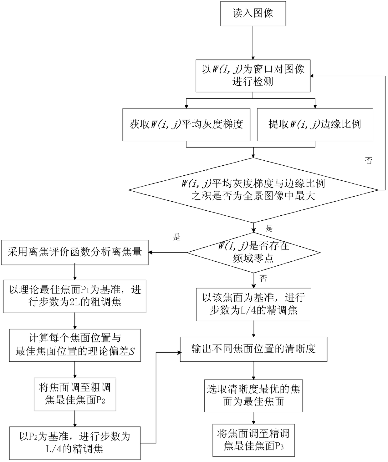
[0060] Such as figure 1 Shown, the realization process of the present invention is:

[0061] 1) Confirm that the on-orbit imaging parameters of the camera are adjusted in place, and obtain the camera's central wavelength, relative aperture, focusing step, focusing magnification, pixel size, focusing range and other parameters, as shown in Table 1;

[0062] Table 1

[0063] serial number

project name

unit

Test / Design Results

1

center wavelength

μm

2

relative aperture

none

3

Focus step

μm

4

Focus magnification

none

5

pixel size

μm

6

Focus range

μm

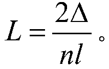
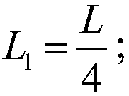
[0064] 2) According to the central wavelength λ obtained in step 1), the reciprocal F of the relative aperture, the focusing step distance l, and the focusing magnification n, calculate the half focal depth of the camera Δ a...


PUM


Abstract

The invention discloses an on-orbit focusing method of a space-borne visible light transmission camera for earth observation. When the defocus of the camera optical system exceeds a certain level, there will be zero points in the frequency domain of the image formed by the camera. According to the defocused camera image, the zero position can be found in the frequency domain. When the position of the zero point in the frequency domain is known, the radius of the point spread function caused by defocus is calculated according to the position of the zero point and the best focal plane position is estimated, and then the focusing direction is judged according to the image clarity formed by different focal plane positions , the position of the best focal plane can be determined; when there is no zero point in the frequency domain of the image, it is already near the position of the best focal plane, and the image sharpness of the nearby focal plane is calculated to judge the focusing direction and determine the position of the best focal plane. The invention ensures the high precision and high efficiency of on-orbit focusing, and improves the on-orbit imaging performance and image quality of the optical remote sensor.

Description

technical field [0001] The invention relates to an on-orbit focusing method of a space-borne visible light transmission camera for earth observation, belonging to the technical field of aerospace optics and remote sensing. Background technique [0002] Camera defocus is an important factor affecting the quality of satellite imaging. After the satellite is launched, the focal plane position of the camera must be rechecked, and the camera should be adjusted on-orbit if necessary. Therefore, in order to improve the on-orbit imaging quality of satellites, it is necessary to carry out research on the on-orbit focusing method of the camera and the judging method of the focusing effect. [0003] At present, the domestic remote sensing cameras all adopt the focusing method of moving the focal plane. In addition to this method, foreign cameras also adopt other methods, such as SPOT-1, SPOT-4, and SPOT-5, which adopt the dual-camera contrast focusing method. Therefore, it is first ne...

Claims


Application Information

Patent Timeline
Patent Type & Authority Patents(China)
IPC IPC(8): H04N5/232G02B7/36
CPCG02B7/36H04N23/67
Inventor 李方琦谭伟齐文雯何红艳邢坤刘薇高慧婷张智江澄曹世翔
Owner BEIJING RES INST OF SPATIAL MECHANICAL & ELECTRICAL TECH
Learn More