Device for manufacturing tempered glass using chemical strengthening and manufacturing method therefor

A chemical tempering and tempering glass technology, which is applied in glass tempering, glass manufacturing equipment, glass transportation equipment, etc., can solve the problems of reducing production productivity, prolonging standby time, and reducing the turnover rate of preheating furnace, so as to shorten the production process time, save replacement costs, and shorten warm-up time

Inactive Publication Date: 2016-10-12
金浩权
View PDF9 Cites 11 Cited by
  • Summary
  • Abstract
  • Description
  • Claims
  • Application Information

AI Technical Summary

Problems solved by technology

[0020] However, according to the prior art, the temperature of the flat glass is raised from normal temperature to about 300-400°C in stages in a preheating furnace to realize preheating. The temperature range between the initial preheating temperature and the final preheating temperature is too large when the flat glass is put in, so there is a problem of preheating after the preheated flat glass is transported to the main furnace until the subsequent flat glass is supplied to the preheating furnace. The problem of extended standby time required
[0021] That is, in the preparatory steps for preheating the subsequent flat glass, it is necessary to lower the temperature inside the preheating furnace from the final preheating temperature (about 400°C) to the initial preheating temperature (normal temperature to about 100°C). Excessively large, therefore, will inevitably lead to prolonged standby time
[0022] Of course, when the tempered glass is continuously produced, the standby process time of the preheating furnace is prolonged, which naturally leads to a decrease in the turnover rate of the preheating furnace, which results in a decrease in overall production productivity.
[0023] Moreover, the disclosed existing tempered glass manufacturing device and manufacturing method have the problems of long process time, low yield, and high defect rate due to glass breakage, etc.

Method used


Image

  • Device for manufacturing tempered glass using chemical strengthening and manufacturing method therefor
  • Device for manufacturing tempered glass using chemical strengthening and manufacturing method therefor
  • Device for manufacturing tempered glass using chemical strengthening and manufacturing method therefor

Examples


Embodiment Construction

[0060] Hereinafter, preferred embodiments of the present invention will be described in detail with reference to the accompanying drawings.

[0061] It should be noted that the accompanying drawings, which illustrate preferred embodiments of the present invention, are not drawn to exact scale and the thickness of lines or the size of components may be exaggerated for descriptive convenience and clarity. In addition, the terms used herein are defined by considering the functions of the present invention, and may be changed according to user's or operator's habit or purpose.

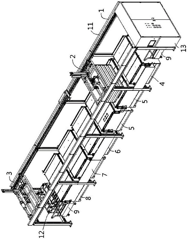
[0062] Such as Figure 4 to Figure 6As shown, the tempered glass manufacturing device according to the present invention includes such as conveying unit parts 200, 201, fixture supply part 300, first preheating part 400, second preheating part 500, chemical tempering part 600, first slow cooling part 700 , the second slow cooling unit 800 , the cleaning unit 900 , and the jig discharge unit 301 are a stru...


PUM

PropertyMeasurementUnit
melting pointaaaaaaaaaa
thicknessaaaaaaaaaa
diameteraaaaaaaaaa

Abstract

The present invention relates to a device for manufacturing tempered glass using chemical strengthening and a manufacturing method therefor. The present invention manufactures tempered glass by raising the temperature of plate glass and preheating the plate glass at first and second preheating units step by step; substituting with potassium ions within a potassium nitrate solution of a chemical strengthening unit; cooling the plate glass through first and second slow cooling processes at first and second slow cooling units; and cleaning the plate glass by fine bubbles while securing stability of the glass at a cleaning unit. Due to this feature, the present invention can maximally shorten the process time for manufacturing tempered glass to considerably enhance yield and improve defect rate, and further can manufacture all types of plate glass such as thin plate glass and thick plate glass into chemically tempered glass regardless of the standard of plate glass.

Description

technical field [0001] The present invention relates to a tempered glass manufacturing device and manufacturing method utilizing chemical tempering, more specifically, to a tempered glass manufacturing device and manufacturing method utilizing chemical tempering, characterized in that the first preheating part and the second preheating part Heat up the temperature of the flat glass in stages to preheat the flat glass, replace it with potassium ions in the potassium nitrate solution in the chemical tempering part, and then go through the first slow cooling process in the first slow cooling part and the second slow cooling part Cooling with the second slow cooling process, cleaning with fine air bubbles in the state where the cleaning part ensures the stability of the glass, thereby adding compressive stress to the surface of the glass to make tempered glass, thereby shortening the manufacturing process to the maximum It takes time to greatly increase the yield, and at the same ...

Claims


Application Information

Patent Timeline
Patent Type & Authority Applications(China)
IPC IPC(8): C03B27/03C03B27/012C03B35/20
CPCC03C21/002C03C23/0075C03B27/012C03B27/03C03B35/20
Inventor 金浩权
Owner 金浩权
Why Eureka
Try Eureka