Cooling device for reductant injection module and selective catalyst reduction system having same

A technology of injection module and cooling device, which is applied in the direction of engine cooling, exhaust device, silencer device, etc., and can solve problems such as blockage, non-circulation of coolant, deformation of reducing agent injection module, etc.

Inactive Publication Date: 2018-10-30
DOOSAN INFRACORE CO LTD
View PDF4 Cites 0 Cited by
  • Summary
  • Abstract
  • Description
  • Claims
  • Application Information

AI Technical Summary

Problems solved by technology

[0003] However, when the engine is stopped, the coolant pump is also stopped, causing said coolant not to circulate
In this case, the reductant injection module is continuously heated by the high-temperature exhaust pipe, there is deformation of the reductant injection module due to heat, or the injection port of the reductant injection module is damaged by solids evaporated from urea water. The problem of clogging

Method used


Image

  • Cooling device for reductant injection module and selective catalyst reduction system having same
  • Cooling device for reductant injection module and selective catalyst reduction system having same
  • Cooling device for reductant injection module and selective catalyst reduction system having same

Examples


Embodiment Construction

[0033] For the embodiments of the present invention disclosed in the text, the specific structural and functional descriptions are listed purely for the purpose of describing the embodiments of the present invention. The embodiments of the present invention can be implemented in various forms and should not be interpreted as Limited to the examples described in the text.

[0034] The present invention can be modified variously and has various forms, and specific examples will be shown in the drawings and described in detail in the text. However, this does not intend to limit the present invention to a specific disclosed form, and it should be understood that all modifications, equivalents, and substitutions included within the spirit and technical scope of the present invention are included.

[0035] Terms such as first and second may be used to describe various constituent elements, but the constituent elements shall not be limited by the terms. The terms may be used for the...


PUM


Abstract

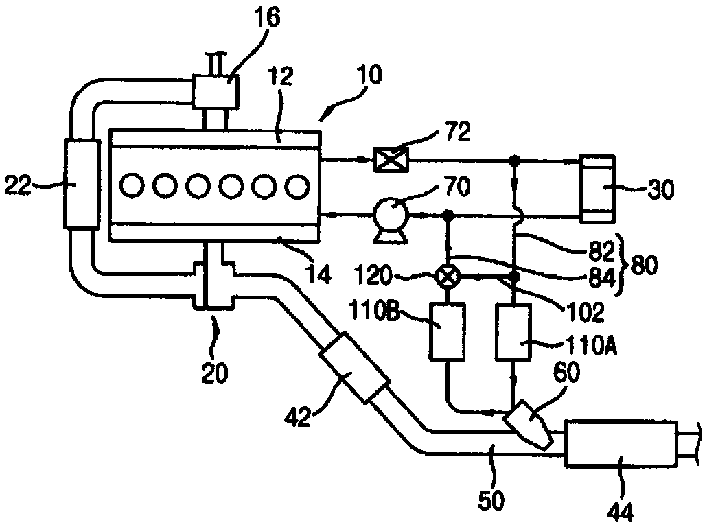
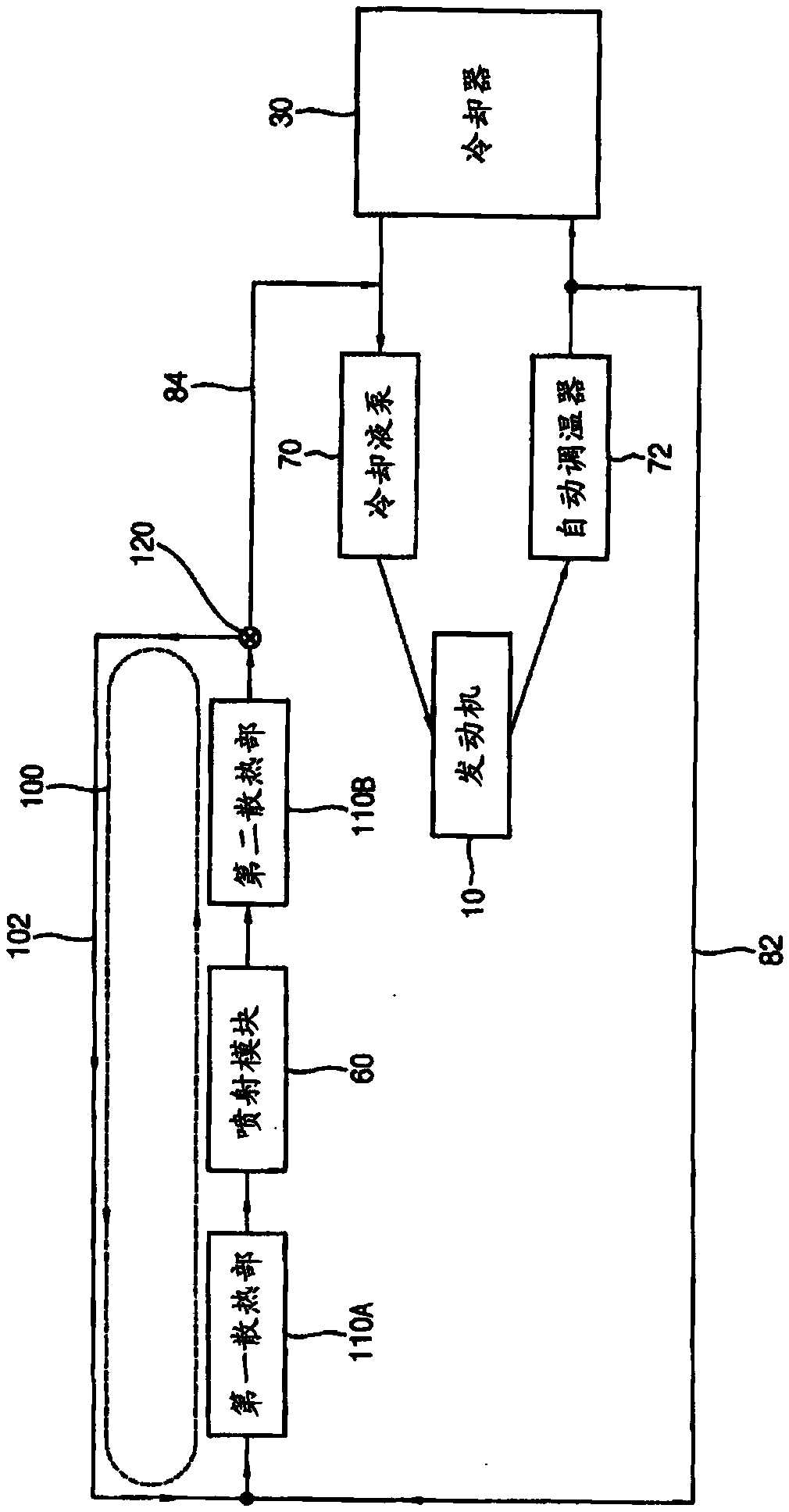
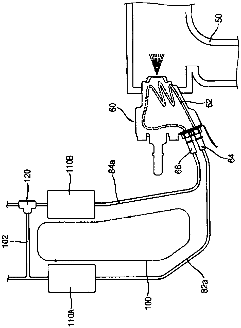
The cooling device of the reductant injection module of the present invention includes: a cooling liquid circulation pipeline, which is connected to the module cooling passage for cooling the reductant injection module, and is used to circulate the cooling liquid; a closed loop circulation pipeline, which is connected to the module cooling The cooling liquid circulation line at the front and rear of the channel is connected so that the cooling liquid circulation line selectively forms a closed circuit; and at least one heat dissipation part is equipped in the closed circuit for releasing the Module cooling channels transfer heat by natural convection.

Description

technical field [0001] The present invention relates to a cooling device for a reductant injection module and a selective catalyst reduction system having the same, and more particularly, to a cooling device for a reductant injection module for exhaust gas aftertreatment of an engine and a selective catalyst reduction system having the same system. Background technique [0002] The selective catalyst reduction device may be provided as an exhaust gas aftertreatment device for reducing pollutants contained in exhaust gas discharged from an engine. The selective catalyst reduction device may include a reducing agent injection module for injecting the reducing agent in a flow direction of the exhaust gas. The engine coolant circulates through the coolant circulation line connected to the reducing agent injection module, so that the reducing agent injection module can be prevented from being heated by high-temperature exhaust gas. [0003] However, when the engine is stopped, ...

Claims


Application Information

Patent Timeline
Patent Type & Authority Patents(China)
IPC IPC(8): F01N3/24
CPCF01N3/208F01N2610/11Y02T10/12B01D53/9418F01N3/2066F01N2610/1453F01P5/10F28D15/02
Inventor 金银炯崔南一
Owner DOOSAN INFRACORE CO LTD
Why Eureka
Try Eureka