A solenoid valve for a compressor

A technology of compressors and solenoid valves, applied in valve details, valve devices, multi-way valves, etc., can solve problems such as short service life, unstable working performance, heavy kinetic energy of moving iron core 2′, etc., and achieve service life Long, stable and reliable working performance

Active Publication Date: 2016-10-19
ZHEJIANG SANHUA COMMERCIAL REFRIGERATION CO LTD
View PDF5 Cites 8 Cited by
  • Summary
  • Abstract
  • Description
  • Claims
  • Application Information

AI Technical Summary

Problems solved by technology

In this process, when the ejector rod 4' collides with the valve core 7', it is necessary to overcome the air pressure received by the valve core 7'. Although the air pressure is not large, because the ejector rod 4' is relatively thin, its rigidity and strength are relatively low, and Both the sealing plug 3' and the ejector rod 4' have no cushioning structure. After working for a certain number of times, the ejector rod 4' is easy to bend and fail, which may cause the valve core 7' to be stuck, resulting in the second flow path B and the third flow path C. The fluid cannot flow smoothly, and it may also damage the second valve port 20' on the small valve seat 6', so that the second valve port 20' cannot be closed under the electrified state
In addition, when the sealing plug 3' is attached to the first valve port 10', since the moving iron core 2' is heavier and the kinetic energy is greater, the impact generated by the sealing plug 3' and the first valve port 10' is relatively large, and a certain life cycle The rear sealing plug 3' is prone to failure, resulting in the failure of the first valve port 10' to seal
[0007] In summary, although the existing solenoid valves for compressors can realize the communication between the high-pressure end and the medium-pressure end of the compressor when the coil components are powered off, there are problems such as easy bending of the ejector rod, easy failure of the sealing plug and the valve core, and unstable working performance. and short service life

Method used


Image

  • A solenoid valve for a compressor
  • A solenoid valve for a compressor
  • A solenoid valve for a compressor

Examples


Embodiment Construction

[0027] The structure and working principle of the solenoid valve for compressor of the present invention will be described in detail below in conjunction with the accompanying drawings.

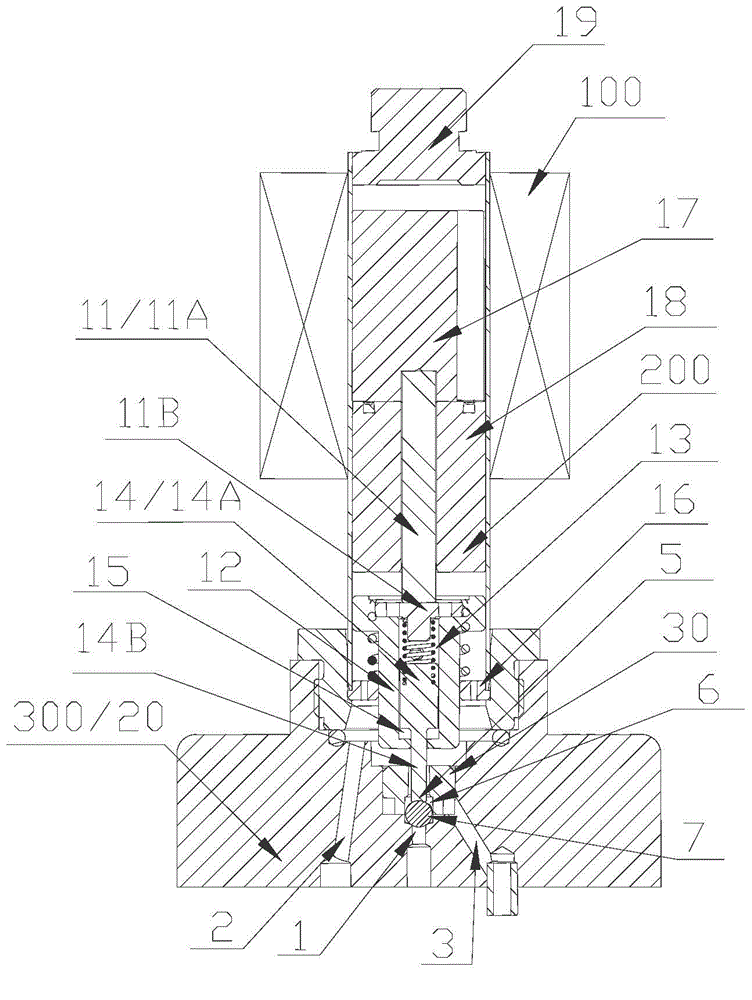
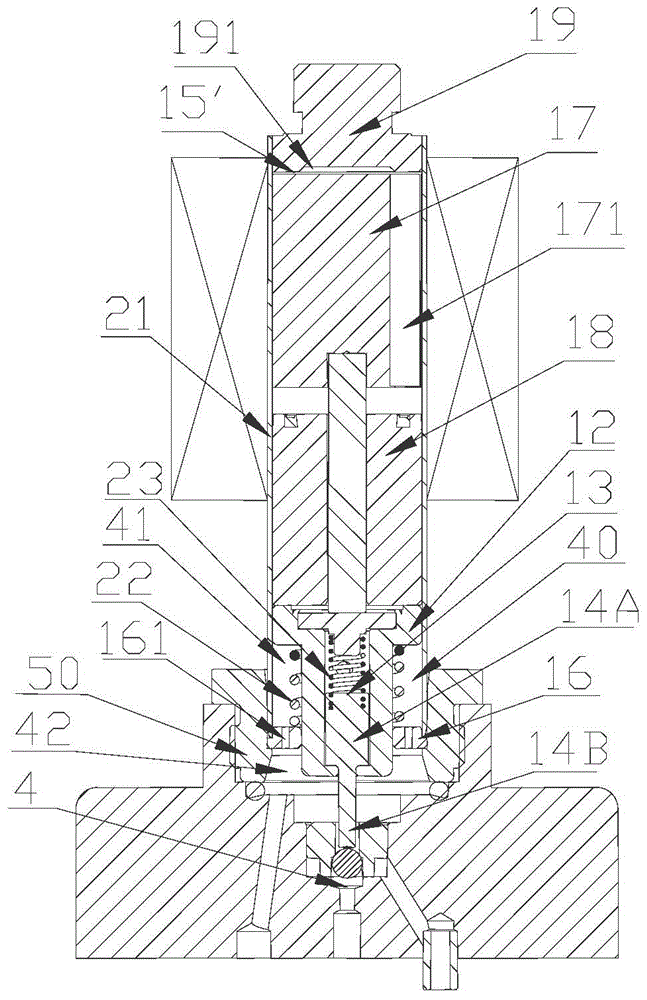
[0028] figure 2 Shown is a schematic structural view of a solenoid valve for a compressor according to a specific embodiment of the present invention under the condition that the coil part is energized; image 3 Shown is a schematic structural view of a solenoid valve for a compressor in a power-off state of a coil part according to a specific embodiment of the present invention; Figure 4 shown as figure 2 Schematic diagram of the transmission sleeve of the solenoid valve used in the medium compressor; Figure 5 shown as figure 2 Bottom view of auxiliary valve seat of solenoid valve for medium compressor.

[0029] Such as Figure 2 to Figure 5 As shown, the solenoid valve for a compressor in this embodiment includes a coil component 100 , a valve body component 200 and a valve seat c...


PUM


Abstract

The invention provides a solenoid valve for compressor. The solenoid valve comprises a coil component, a valve body component and a valve seat component. The valve seat component comprises an inflow channel, an outflow channel, and a bypass channel. The valve seat component also comprises a main valve port and an auxiliary valve port, and a valve cavity is formed between the main valve port and the auxiliary valve port; a valve element is arranged in the valve cavity; when the coil component is electrified, the valve element closes the main valve port and opens the auxiliary valve port, so that the bypass channel communicates with the outflow channel; when the power for the coil component is cut, the valve element closes the auxiliary valve port and opens the main valve port, so that the bypass channel communicates with the inflow channel. When the power for the coil component is cut, the valve element closes the auxiliary valve port, so that the bypass channel communicates with the inflow channel. The solenoid valve meets the requirement of a loaded state in a power-cut state of a compressor, and is long in service life and stable and reliable in work performance.

Description

technical field [0001] The invention belongs to the technical field of refrigeration control systems, and in particular relates to a solenoid valve for a compressor. Background technique [0002] In a vapor compression refrigeration device, the compressor is one of the main components. The compressor compresses the refrigerant medium from a low-pressure state to a high-pressure state, creating conditions for the refrigerant liquid to be refrigerated at low temperature in the evaporator and liquefied at room temperature in the condenser. In addition, because the compressor continuously inhales and discharges gas, the refrigeration cycle can be repeated, so it is called the "heart" of the entire device. In order to accurately control the flow direction of the fluid in the compressor, more and more solenoid valves for compressors are used on the compressor. [0003] figure 1 Shown is a structural schematic diagram of an existing solenoid valve used in a compressor in a power...

Claims


Application Information

Patent Timeline
Patent Type & Authority Applications(China)
IPC IPC(8): F16K31/06F16K11/04
CPCF16K11/04F16K31/0603
Inventor 不公告发明人
Owner ZHEJIANG SANHUA COMMERCIAL REFRIGERATION CO LTD
Why Eureka
Try Eureka