Motor driving device having motor stopping setting and driving method thereof

A motor drive and motor technology, applied to the motor drive device with motor stop setting and its drive field, can solve the problems of the motor speed cannot be adjusted, the curve of the motor speed cannot be adjusted, etc., to reduce loss and improve work efficiency Effect

Inactive Publication Date: 2016-10-19
AMTEK SEMICON
View PDF6 Cites 2 Cited by
  • Summary
  • Abstract
  • Description
  • Claims
  • Application Information

AI Technical Summary

Problems solved by technology

[0002] The motor drive method is often based on Pulse Width Modulation (PWM), and the output speed of the motor has a linear relationship with the input duty cycle (Duty cycle), but the curve of the motor speed cannot be adjusted. In order to solve the problem of motor To solve the problem that the speed cannot be adjusted, US Patent No. 8,847,537 proposes a motor drive device with speed setting and its driving method. The motor drive device is as follows: figure 1 As shown, the motor drive device includes a PWM conversion circuit 10, an oscillation circuit 11, a comparator 12, and a control unit 13. Through the PWM conversion circuit 10, the input control signal 101 and the adjustable maximum set voltage signal (VH) 102 And the adjustable minimum setting voltage signal (VL) 103 is converted into an analog signal (VTH), and then the analog signal is compared with the triangular wave signal (TRI) generated by the oscillation circuit 11, and compared by the comparator 12 to output The drive signal is sent to the control unit 13 to control the speed of the motor 14

Method used


Image

  • Motor driving device having motor stopping setting and driving method thereof
  • Motor driving device having motor stopping setting and driving method thereof
  • Motor driving device having motor stopping setting and driving method thereof

Examples


Embodiment Construction

[0031] Since the present invention discloses a motor drive device with a motor stop setting, the basic principle and function of the motor rotation used therein have been understood by those with ordinary knowledge in the relevant technical field, so the following description will not be repeated. for a full description. At the same time, the diagrams compared below are schematic representations of structures and functions related to the features of the present invention, and are not completely drawn according to actual dimensions, so please describe them first.

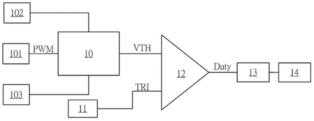
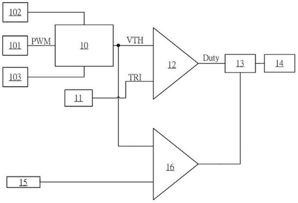
[0032] The present invention relates to a motor drive device with a motor stop setting, especially a motor drive device including a PWM conversion circuit, an oscillation circuit, a first comparator, a second comparator and a control unit.

[0033] First, see figure 2 , is a schematic diagram of the motor drive device of the present invention.

[0034] Such as figure 2 As shown, the motor driving device is compo...


PUM


Abstract

The invention discloses a motor drive device having motor stopping setting and a driving method thereof. The motor driving device having the motor stopping setting consists of a pulse-width modulation conversion circuit, an oscillation circuit, a first comparator, a second comparator and a control unit; after comparing an adjustable stopping setting signal with a simulation signal, the second comparator is used for outputting the stopping setting signal to the control unit; the control unit receives a driving signal outputted by the first comparator and the stopping setting signal outputted by the second comparator in order to determine the work cycle by the time the motor stops. As a result, the motor driving device having motor stopping setting and the driving method thereof can reduce the motor energy loss and improve motor working efficiency.

Description

technical field [0001] The present invention relates to a motor driving device and its driving method, in particular to a motor driving device and its driving method which can be set to stop the motor. The driving method thereof can reduce the energy loss of the motor, improve the working efficiency of the motor, and achieve the purpose of energy saving and carbon reduction. Background technique [0002] The motor drive method is often based on Pulse Width Modulation (PWM), and the output speed of the motor has a linear relationship with the input duty cycle (Duty cycle), but the curve of the motor speed cannot be adjusted. In order to solve the problem of motor To solve the problem that the speed cannot be adjusted, US Patent No. 8,847,537 proposes a motor drive device with speed setting and its driving method. The motor drive device is as follows: figure 1 As shown, the motor drive device includes a PWM conversion circuit 10, an oscillation circuit 11, a comparator 12, an...

Claims


Application Information

Patent Timeline
Patent Type & Authority Applications(China)
IPC IPC(8): H02P3/18
CPCY02P80/10
Inventor 李灯辉余国庸
Owner AMTEK SEMICON
Why Eureka
Try Eureka