Spiral bevel gear machining method

A technology of spiral bevel gears and processing methods, which is applied in the directions of belts/chains/gears, gear teeth, elements with teeth, etc., can solve the problems of complex calculation and adjustment, and achieves the improvement of adjustment efficiency, elimination of diagonal contact, improvement of Effect of tooth flank contact area

Inactive Publication Date: 2016-10-26
TIANJIN UNIV
View PDF4 Cites 1 Cited by
  • Summary
  • Abstract
  • Description
  • Claims
  • Application Information

AI Technical Summary

Problems solved by technology

[0005] The purpose of the present invention is to provide a method for processing spiral bevel gears, which is mainly aimed at small wheels (that is, intermeshing spirals) to overcome the disadvantages of diagonal contact in the contact area and complex calculation and adjustment of gear cutting caused by traditional spiral bevel gear processing methods. The spiral bevel gear with fewer teeth in the bevel gear pair) is improved, and the bull wheel (that is, the spiral bevel gear with more teeth in the meshing spiral bevel gear pair) is still processed by the generating method, and the spiral bevel gear is processed by the method of the present invention. Bevel gear pairs eliminate diagonal contact and make adjustment calculations simpler

Method used


Image

  • Spiral bevel gear machining method
  • Spiral bevel gear machining method

Examples


Embodiment

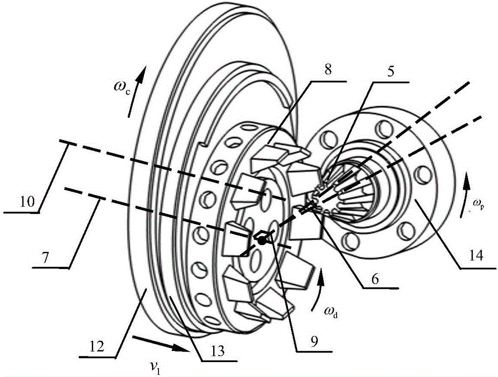
[0030] In this embodiment, the spiral bevel gear processing is carried out based on a horizontal gear milling machine tool. In order to intuitively describe the kinematic relationship between the various parts of the machine tool during the machining process, the "extraction" of the table part that highlights the machine tool movement is analyzed, as shown in figure 2 shown. This part comprises gear blank 5, small wheel cutter head 8, cradle 12, eccentric drum 13, workpiece case 14, wherein, eccentric drum 13 is installed on the cradle 12 eccentrically with certain eccentric distance, and small The wheel cutter head 8 is eccentrically installed on the eccentric drum 13 again, and the axes of the small wheel cutter head 8, the cradle 12 and the eccentric drum 13 are parallel to each other. In the above process, the eccentricity of the installation of the eccentric drum 13 and the installation of the lower wheel cutter head 8 are related to the structure of the machine tool, an...


PUM


Abstract

The invention discloses a spiral bevel gear machining method. The spiral bevel gear machining method is mainly characterized in that as for machining of a less-teeth bevel gear in a meshed spiral bevel gear pair, the axis of a machining cutter is perpendicular to a surface cone generatrix of the to-be-machined gear in mounting and positioning of the gear, and feed movement of the cutter axially along a shake plate needs to be added on the basis of regular movement of the cutter in the machining process. The machining method includes cutter setting, gear blank positioning and cutter cutting movement for forming tooth grooves. Cutter resultant movement includes rotational movement of the cutter along own axis, rotation movement of the cutter identical to the shake plate in angular speed, feeding movement of the cutter along the rotation axis of the shake plate and rotation movement of a gear blank along own axis. After a complete tooth groove is formed by machining, the gear blank is subjected to indexing, and the shake plate drives the cutter to rotate to an initial set cutting position. The cutting process is repeated until machining of all tooth grooves of the gear is finished.

Description

technical field [0001] The invention belongs to a processing method of a spiral bevel gear, and in particular relates to a processing method of a spiral bevel gear by denatured generation method. Background technique [0002] Spiral bevel gears are widely used in automobile manufacturing, shipbuilding and other fields because of their large transmission ratio, high coincidence degree, and suitable for power transmission between staggered shafts. Among them, tapered teeth occupy a major position in its application. However, when the traditional processing method is used to cut the tooth surface of the tapered spiral bevel gear, in order to process the tooth surface and the tooth root surface at the same time, the tool tip plane of the large wheel and the small wheel should be consistent with the surface of the large wheel and the small wheel. The root cone surface is tangent, that is, the axes of the big wheel and the small wheel cutterhead should be perpendicular to the roo...

Claims


Application Information

Patent Timeline
Patent Type & Authority Applications(China)
IPC IPC(8): B23F9/08
CPCB23F9/08
Inventor 孙月海李小亨
Owner TIANJIN UNIV
Why Eureka
Try Eureka