Concentricity calibrating device and method for assembling of azimuth compass repeater

A calibration device and technology of concentricity, applied in metal processing, metal processing equipment, manufacturing tools, etc., can solve the problems of difficult to precisely control the matching clearance of the transmission mechanism, high processing cost, unable to guarantee the four-center coincidence accuracy, etc., to avoid concentricity. The accuracy of the accuracy is not up to standard, the number of rework is reduced, and the processing cycle is shortened.

Active Publication Date: 2016-10-26
CSSC MARINE TECH CO LTD
View PDF9 Cites 2 Cited by
  • Summary
  • Abstract
  • Description
  • Claims
  • Application Information

AI Technical Summary

Problems solved by technology

[0005] The purpose of the present invention is to solve the problem of high processing cost due to the need to ensure the coincidence of the four centers in the manufacturing process of the above-mentioned azimuth compass, and the problem that the accuracy of the coincidence of the four centers cannot be guaranteed due to the difficulty in accurately controlling the matching clearance of the transmission mechanism. Provide a concentricity calibration device for azimuth compass assembly

Method used


Image

  • Concentricity calibrating device and method for assembling of azimuth compass repeater
  • Concentricity calibrating device and method for assembling of azimuth compass repeater
  • Concentricity calibrating device and method for assembling of azimuth compass repeater

Examples


Embodiment 1

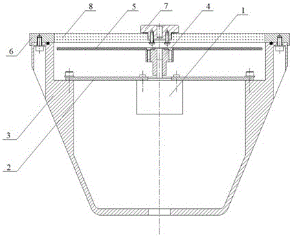
[0048] Such as Figure 1-16 As shown, this embodiment is used for the concentricity calibration device for the assembly of the azimuth compass. The assembly structure of the azimuth compass is: the drive motor 1 is fixed on the casing 3 through the base plate 2, and the drive motor 1 drives the dial through the transmission mechanism 4. 5 rotates, the side angle ring 6 is fixed on the casing 3, and the positioning block 7 is fixed on the side angle ring 6 through the observation glass 8;

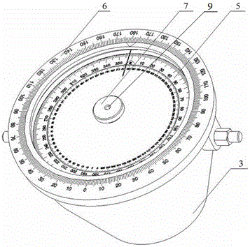
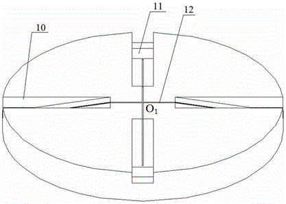
[0049]The concentricity calibration device includes a first calibration unit, a second calibration unit and an optical azimuth 19, and the first calibration unit is used to calibrate the concentricity between the scale center of the side angle ring 6 and the center hole 9 of the positioning block 7 degree, the first calibration unit is a cylinder, and at least four inverted trapezoidal grooves 10 are arranged on the upper end surface of the cylinder, and the four inverted trapezoidal grooves...

Embodiment 2

[0067] This embodiment is used for the concentricity calibration device assembled by the azimuth compass. In this embodiment, the number of inverted trapezoidal grooves in the first calibration unit is 6, and the corresponding observation holes are 6. The first calibration unit is used for When calibrating the concentricity between the scale center of the sheer angle circle and the center hole of the positioning block, observe the scale of the sheer angle circle through 6 observation holes to improve the calibration accuracy, or set the inverted trapezoidal groove in the first calibration unit The number is set to 9, and the corresponding observation holes are 9, or a greater number of inverted trapezoidal grooves and observation holes are required for more precision, so as to optimize the calibration accuracy, and other technical solutions are the same as in Example 1 .


PUM


Abstract

The invention relates to a concentricity calibrating device for assembling of an azimuth compass repeater. The concentricity calibrating device is characterized in that the concentricity calibrating device comprises a first calibrating unit, a second calibrating unit and an optical azimuth instrument. The first calibrating unit is used for calibrating the concentricity between the scale center of a board angle circle and a central hole of a positioning block, the second calibrating unit is used for calibrating the concentricity between the rotating axis and the scale center of a dial, and the optical azimuth instrument is used for calibrating the concentricity between the scale center of the board angle circle and the scale center of the dial. According to the concentricity calibrating device for assembling of the azimuth compass repeater, the problems that in the manufacturing process of the azimuth compass repeater, the machining cost is high due to the fact that four-center superposition needs to be ensured, and four-center superposition precision cannot be guaranteed due to the fact that the fit clearance of a transmission mechanism is hard to control precisely are solved.

Description

technical field [0001] The invention belongs to the technical field of ship navigation, and in particular relates to a concentricity calibration device and a calibration method for azimuth compass assembly. Background technique [0002] The azimuth compass is generally installed on the central axis of the ship or on both sides, and the heading angle of the ship is displayed repeatedly by the dial. During the navigation of the ship, an azimuth reading instrument is often set up on the azimuth compass to measure the angle of the object or the azimuth of the gyro. [0003] During the assembly process of the azimuth compass, the rotation axis of the dial, the scale center of the dial, the scale center of the sheer circle, and the center hole of the positioning block must coincide, otherwise eccentricity errors will occur. And this error is not a fixed error, it will change with the observation direction and the rotation angle of the dial, and it cannot be compensated by rotatin...

Claims


Application Information

Patent Timeline
Patent Type & Authority Applications(China)
IPC IPC(8): B23P19/10
CPCB23P19/102
Inventor 沈旻雅蔡忠仁彭朝晖
Owner CSSC MARINE TECH CO LTD
Why Eureka
Try Eureka