Device, method and system for row-by-row feeding of material tubes

A material reclaiming device and material pipe technology, applied in metal processing and other directions, can solve the problems of high labor intensity, single repetitive labor, waste of human and material resources, etc. Effect

Active Publication Date: 2018-01-19
GREE ELECTRIC APPLIANCES INC
View PDF4 Cites 0 Cited by
  • Summary
  • Abstract
  • Description
  • Claims
  • Application Information

AI Technical Summary

Problems solved by technology

[0002] Existing automation equipment requires long U-tubes (for example: long U-shaped copper tubes) to be fed in rows horizontally. In order to protect the U-shaped copper tubes from being crushed or pinched, they are now manually loaded, which is extremely labor-intensive and Manual feeding is a single repetitive labor, the production efficiency is extremely low, and a lot of manpower and material resources are wasted
However, the mechanical structure is used to complete the retrieving of the material tube, which is easy to cause damage to the material tube
There is also the problem of damage to the material pipe by manual operation.
[0003] In the existing technology, there are defects such as high labor intensity, low production efficiency and high cost, and it is easy to cause damage to the material tube

Method used


Image

  • Device, method and system for row-by-row feeding of material tubes
  • Device, method and system for row-by-row feeding of material tubes
  • Device, method and system for row-by-row feeding of material tubes

Examples


Embodiment 1

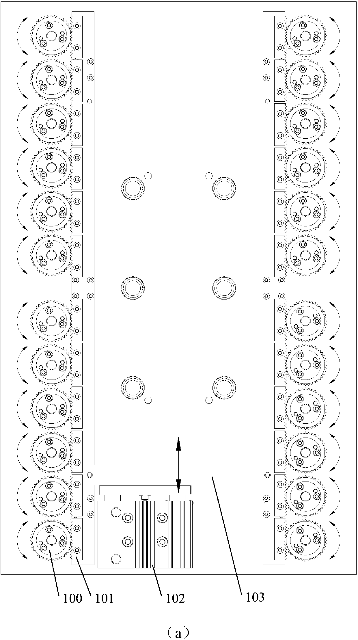
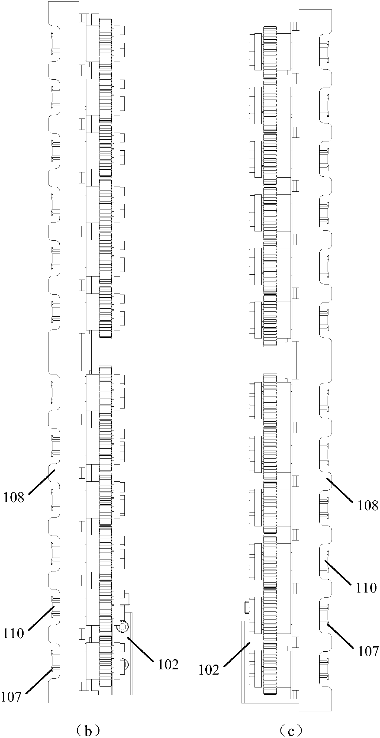
[0034] Such as Figure 1-5 As shown, the row-by-row reclaiming device for material tubes described in the embodiment of the present invention includes a base 108, two rows of rotating shafts 110 passing through the base 108, located above the base 108, and fixedly installed on the The swing mechanism of the rotating shaft 110 (preferably such as: gear 100 and rack 101; pendulum 105 and connecting rod 104), is located below the base 108 and is fixedly installed with the clamping mechanism of the rotating shaft 110 (for example: fixed on elongated plate or jaw 107 on the rotating shaft 110), and a driving mechanism (such as an air cylinder 102) that drives the swing of the swing mechanism; wherein,

[0035] Driven by the drive mechanism, the swing mechanism swings and drives the rotating shaft to rotate, and the rotating shaft 110 drives the clamping mechanism to rotate. When it is turned to the first position, the material tube is clamped between the clamping mechanism and the...

Embodiment 2

[0041] Such as Figure 1-5As shown, in this embodiment, on the basis of Embodiment 1, an accommodating portion 112 is provided at the bottom of the base 108 close to the rotating shaft 110, and the accommodating portion 112 is used for accommodating the material tube (such as Long straight tube or long U-shaped copper tube 106); Wherein, when the clamping mechanism turns to the first position, the material tube is clamped between the clamping mechanism and the accommodating part 112. Wherein, the tube length of the material tube is preferably 500-1500 mm.

[0042] Through the accommodating portion provided at the bottom of the base, when the clamping mechanism is turned to the first position, the material tube can be more stably clamped between the clamping mechanism and the accommodating portion, so that The material is more reliable and efficient, and it is also conducive to improving the versatility and flexibility of row-by-row retrieving; in addition, the setting of the ...

Embodiment 3

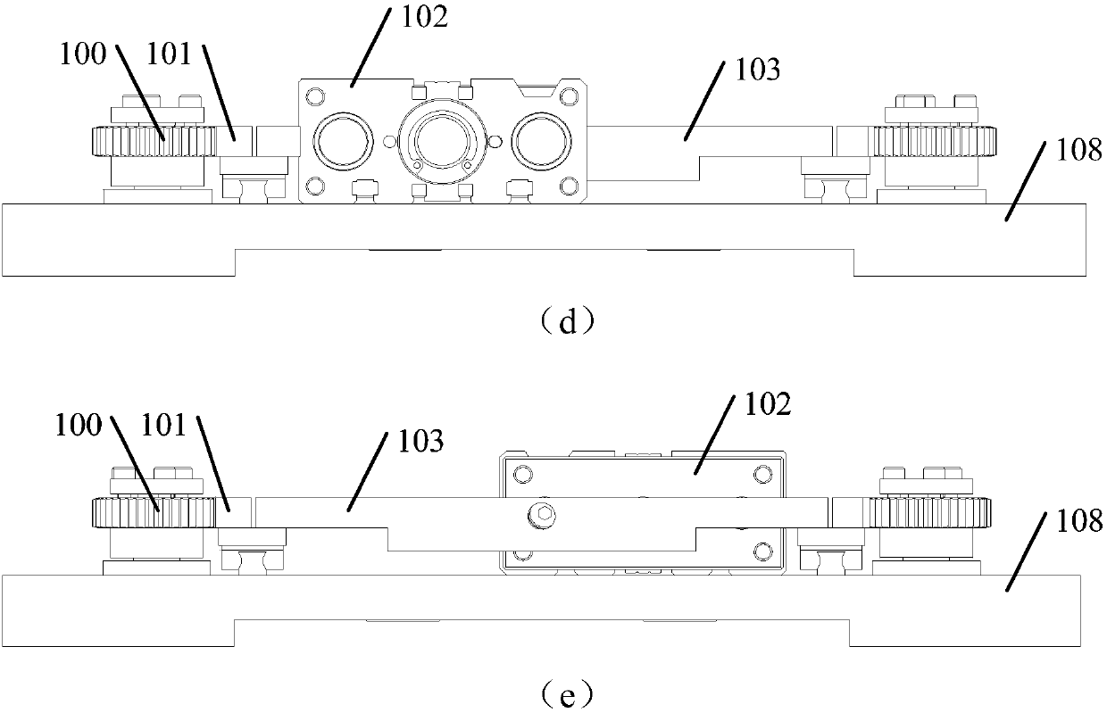
[0050] Such as figure 1 , image 3 As shown, this embodiment is based on Embodiment 1 and Embodiment 2. Preferably, the swing mechanism includes a gear 100 and a rack 101, the gear 100 is fixed on the rotating shaft 110, and the rack 101 and the rack 101 The drive mechanism is connected; the gear 100 is meshed with the rack 101; the drive mechanism is connected with the rack 101.

[0051] In this embodiment, the driving mechanism preferably uses an air cylinder 102 .

[0052] For example: the cylinder 102 includes a piston rod, the front end of the piston rod is provided with a push rod 103, and both ends of the push rod 103 are fixedly connected to the swing mechanism.

[0053] For the structure in which the swing mechanism is a rack and pinion, both ends of the push rod 103 are fixedly connected to the two racks 101 respectively. The rack 101 meshes with the gear 100 , the gear 100 is driven to rotate through the rack 101 , and the clamping mechanism is driven to rotate t...


PUM


Abstract

The invention discloses a reclaiming device for tubes in rows. The reclaiming device comprises a base, two rows of rotary shafts penetrating through the base, a swing mechanism located above the base and fixedly installed on the rotary shafts, a clamping mechanism located below the base and fixedly installed on the rotary shafts, and a driving mechanism driving the swing mechanism to swing, wherein the swing mechanism swings under the driving of the driving mechanism; the clamping mechanism is driven to rotate through the rotary shafts, and when the clamping mechanism rotates to a first position, the tubes are clamped between the clamping mechanism and the bottom of the base; and when the clamping mechanism rotates to a second position, the tubes break away from the clamping mechanism. By means of the scheme, the defects that the labor intensity is large, production efficiency is low and the cost is high in the prior art can be overcome, and the beneficial effects of low labor intensity, high production efficiency and low cost can be realized. The invention further provides a reclaiming and discharging method for the tubes and a reclaiming and discharging system for the tubes.

Description

technical field [0001] The invention relates to the technical field of automatic control, in particular to a device, method and system for row-by-row feeding of material pipes. Background technique [0002] Existing automation equipment requires long U-tubes (for example: long U-shaped copper tubes) to be fed in rows horizontally. In order to protect the U-shaped copper tubes from being crushed or pinched, they are now manually loaded, which is extremely labor-intensive and Manual feeding is a single repetitive labor, the production efficiency is extremely low, and a lot of manpower and material resources are wasted. However, adopting a mechanical structure to complete the retrieving of the material pipe is easy to cause damage to the material pipe. There is also the problem of causing damage to the material pipe by manual operation. [0003] In the prior art, there are defects such as high labor intensity, low production efficiency and high cost, and it is easy to cause d...

Claims


Application Information

Patent Timeline
Patent Type & Authority Patents(China)
IPC IPC(8): B23Q7/04B23Q7/14
CPCB23Q7/042B23Q7/1478
Inventor 尹显椿朱岳刚邱雄胜吴望雄张保全李爽
Owner GREE ELECTRIC APPLIANCES INC
Why Eureka
Try Eureka