
Precise mold of vehicle accumulator shell injection molding parts

A technology of precision molds and batteries, applied in household components, household appliances, other household appliances, etc., can solve problems such as difficult and uniform injection molding, achieve the effect of short molding cycle, clear surface pattern and marking, and avoid plastic parts bubbles

Active Publication Date: 2016-10-26
思柏精密科技股份有限公司
View PDF6 Cites 15 Cited by
  • Summary
  • Abstract
  • Description
  • Claims
  • Application Information

AI Technical Summary

Problems solved by technology

The battery case needs to have the characteristics of corrosion resistance and high temperature resistance, so the mold for injection molding of the car battery case should have uniform and stable molding, long service life, high precision, simple production process, low energy consumption and high quality after molding. The precision of the product is high. Since the automobile battery case is an injection molded part with a large volume and many ribs, some special structures must be needed to solve the practical problems in the prior art that it is difficult to achieve uniform injection molding and non-destructive demoulding due to the many ribs in the product. The design simplifies the structure of the automobile battery shell mold, so that the parting surface of the product is simple, the hot melt material is evenly filled, and the demoulding is easy, which makes the design of the automobile battery shell mold more reasonable

Method used


Image

  • Precise mold of vehicle accumulator shell injection molding parts
  • Precise mold of vehicle accumulator shell injection molding parts
  • Precise mold of vehicle accumulator shell injection molding parts

Examples


Embodiment 1

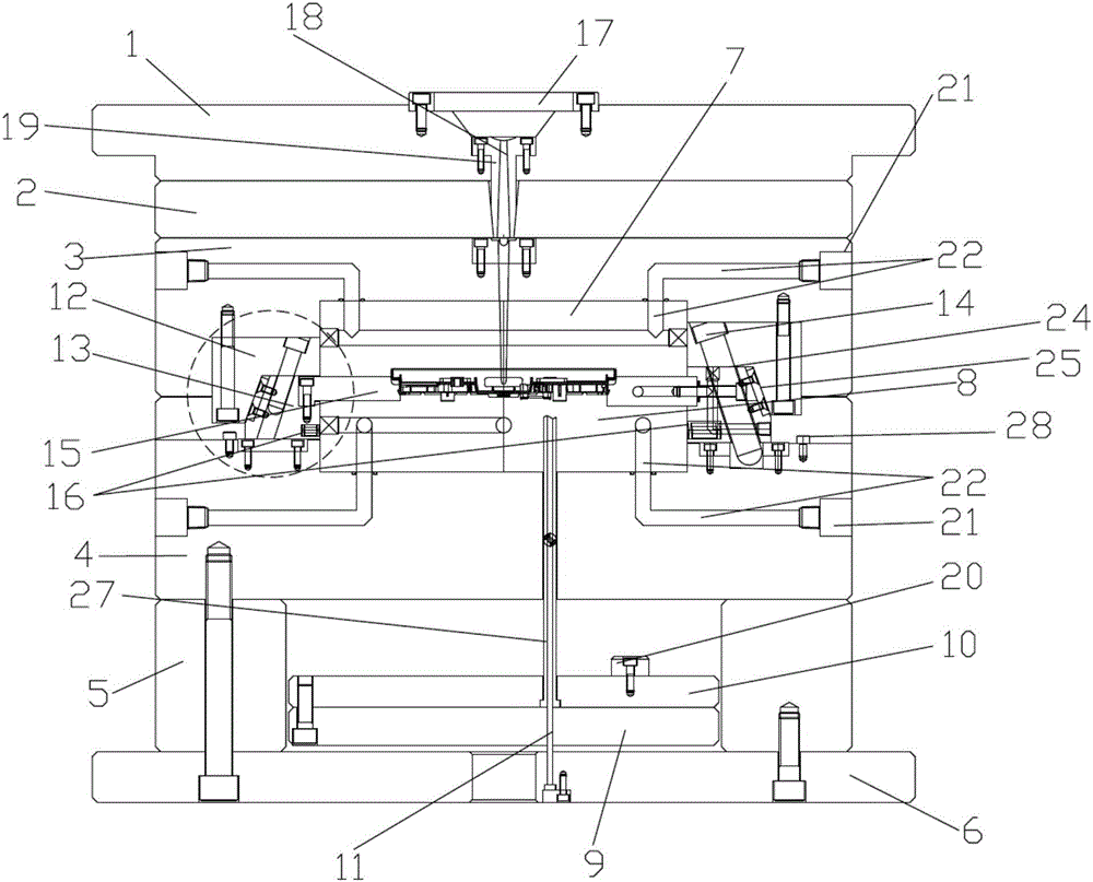
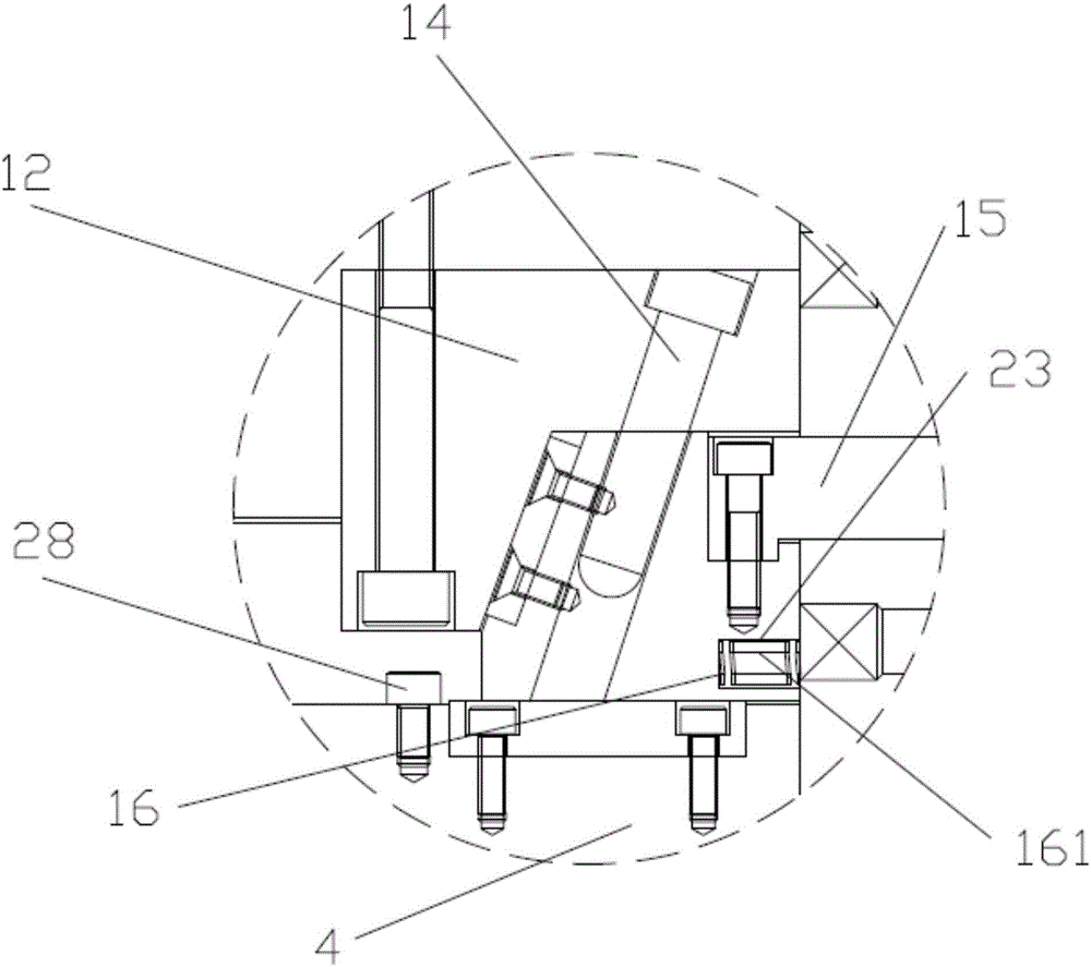
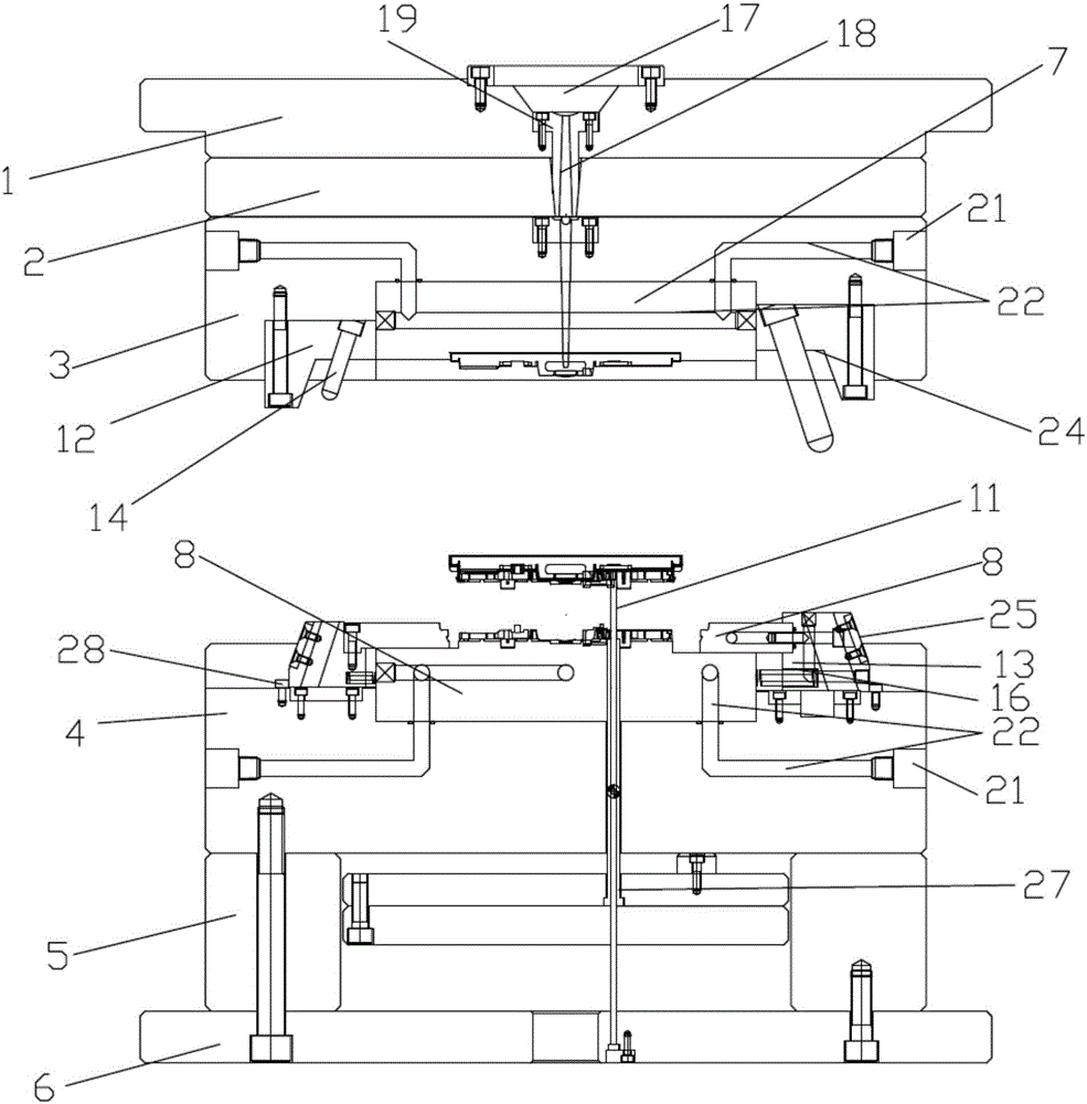
[0022] Such as figure 1 , figure 2 , image 3 with Figure 4 As shown, the precision mold for the injection molded part of the automobile battery case described in this embodiment includes a front mold and a rear mold that are matched with each other, and the front mold includes a front mold fixing plate 1, a nozzle plate 2, and an upper mold from top to bottom. Template 3 and front mold core 7, the rear mold includes a rear mold core 8, a lower template 4, a mold foot 5 and a rear mold fixing plate 6 from top to bottom, and the front mold fixing plate 1 is provided with a positioning ring 17, A sprue bushing 19 is provided below the positioning ring 17, and a runner 18 is arranged inside the sprue bushing 19. It is characterized in that: the front mold core 7 is fixed on the bottom surface of the upper template 3, and the rear mold core 8 is fixed on the The top surface of the upper template 3 corresponds to the position of the front mold core 7. After the mold is closed,...


PUM


Abstract

The invention discloses a precise mold of vehicle accumulator shell injection molding parts. The precise mold comprises a front mold and a back mold; a front mold core is fixed on an upper template; a back mold core is fixed on the upper template, and is opposite to the front mold core; the front mold core and the back mold core are closed to form a product mold cavity; a core pulling slide block is arranged at the side part of the mold cavity, and is embedded between the front mold core and the back mold core; slide blocks are arranged at two side parts of the back mold core; the core pulling slide block is connected to the slide blocks; the two slide blocks are guided to slide through two inclined guide columns relatively independently arranged; the inclined guide columns are fixed at two side parts of the front mold core, and the lower end parts are inserted in the slide blocks; the lower side of a runner is communicated with the mold cavity; and a return device is arranged between the back mold core and the slide blocks. The precise mold of the vehicle accumulator shell injection molding parts improves the product performance of the injection molding parts, is short in molding period and high in production efficiency, is low in wear of an accumulator mold by a flux, and can mold the injection molding parts with complex shapes, clear surface patterns and marks and high size precision in large batches.

Description

technical field [0001] The invention relates to a precision mold, in particular to a precision mold for an injection molded part of an automobile accumulator shell. Background technique [0002] A car battery is a device that converts chemical energy into electrical energy and is a DC power supply. The battery case needs to have the characteristics of corrosion resistance and high temperature resistance, so the mold for injection molding of the car battery case should have uniform and stable molding, long service life, high precision, simple production process, low energy consumption and high quality after molding. The precision of the product is high. Since the automobile battery case is an injection molded part with a large volume and many ribs, some special structures must be needed to solve the practical problems in the prior art that it is difficult to achieve uniform injection molding and non-destructive demoulding due to the many ribs in the product. The design simpl...

Claims


Application Information

Patent Timeline
IPC IPC(8): B29C45/33B29C45/40B29C45/72B29L31/00
CPCB29C45/33B29C45/4005B29C45/72B29L2031/7146
Inventor 姜校平戚永幸上田雄史
Owner 思柏精密科技股份有限公司
Learn More