Chassis for full electric vehicle

A pure electric vehicle and chassis technology, applied in the direction of electric power units, power units, vehicle components, etc., can solve the problems of unoptimized safety, prolonged charging time of the battery box, lack of overall protection of the battery box, etc., and achieve simple structure , Compact layout, satisfying the effect of installation and positioning

Active Publication Date: 2016-10-26
河北中能格瑞电动汽车有限公司
View PDF6 Cites 2 Cited by
  • Summary
  • Abstract
  • Description
  • Claims
  • Application Information

AI Technical Summary

Problems solved by technology

[0002] Due to the constraints of the engine system and transmission system of traditional fuel vehicles, the manufacturing structure of the chassis is complex, the cost is high, and the carrying capacity, light weight, driving stability and safety cannot be optimized
But for pure electric vehicles, one of the most critical issues is balance and stability, and for balance and stability, the biggest constraint is the installation and installation structure of the battery box with the largest weight; the battery box is the main energy storage device of electric vehicles, and its The size of the capacity is directly related to the mileage of the electric vehicle. Therefore, in the existing technology, in order to balance the weight and the center of gravity, the battery box is not installed at the front and rear ends of the vehicle, but is installed in the middle of the chassis by means of slide rails. However, it brings problems such as prolonging the charging time of the battery box or difficulty in replacing the battery box.
In addition, in the event of a collision, the existing pure electric vehicles can only provide protection for the occupants under severe impact, or protect the vehicle and personnel by improving the structure of the bumper, and lack protection for the battery box in the event of a collision. Overall protection, and the resulting damage to the battery box may cause secondary injury to people in the electric vehicle

Method used


Image

  • Chassis for full electric vehicle
  • Chassis for full electric vehicle
  • Chassis for full electric vehicle

Examples


Embodiment Construction

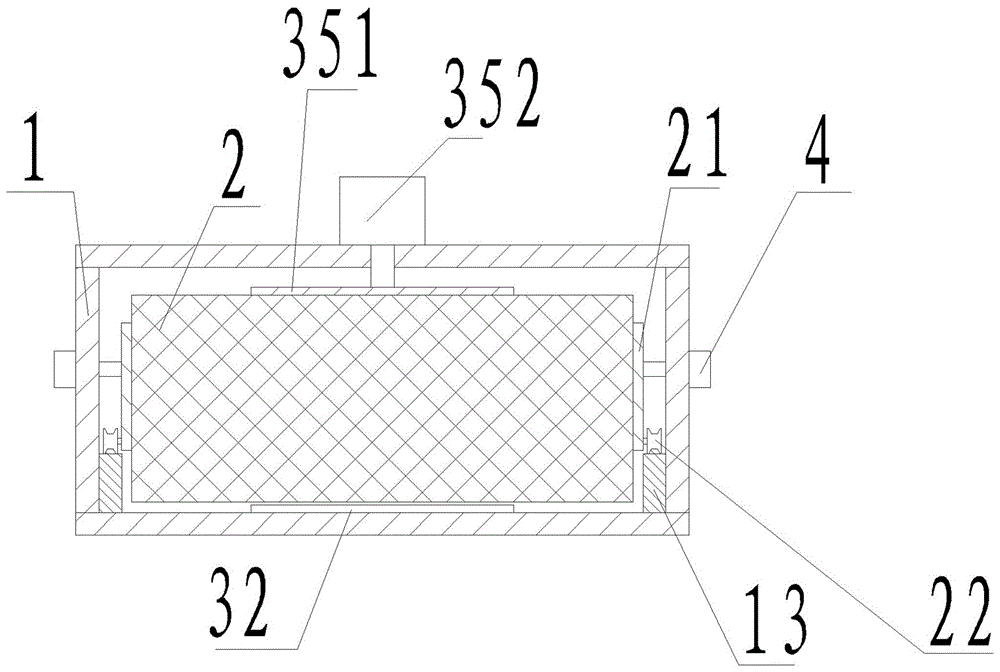
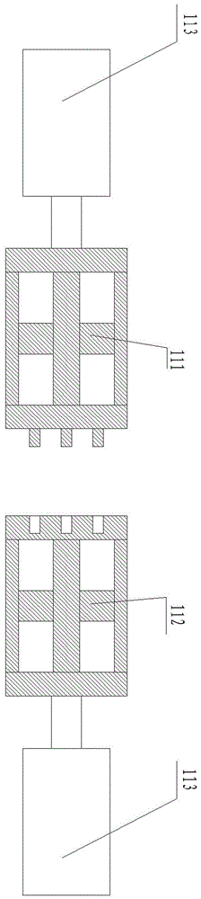
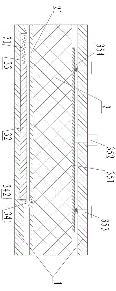
[0021] See attached Figure 1-4 , a chassis for pure electric vehicles, including a chassis frame supporting the weight of the vehicle body and a wheel assembly, a drive mechanism, a steering assembly, a brake assembly and a bumper arranged on the chassis frame, and the chassis frame includes The warehouse-type longitudinal beam 1 on the central axis of the chassis. The warehouse-type longitudinal beam 1 has a through structure, and the front and rear ends are respectively provided with a front sealing door 11 and a rear sealing door 12. Inside the warehouse-type longitudinal beam 1, the longitudinal guide mechanism The battery box 2 is installed and positioned with the positioning mechanism, and the emergency braking device for the battery box 2 is formed by means of the wedge-shaped brake shoe structure arranged at the bottom of the warehouse-type longitudinal beam 1 .

[0022] See attached figure 2 , 4 , the wedge-shaped brake shoe structure includes a wedge-shaped groov...


PUM


Abstract

The invention discloses a chassis for a full electric vehicle, and belongs to the technical field of electric vehicle chassis. The chassis comprises a chassis frame for supporting the weight of a vehicle body, and a wheel assembly, a driving mechanism, a steering assembly, a braking assembly and a bumper which are arranged on the chassis frame. The chassis frame comprises a bin-type longitudinal beam arranged on the axis of the chassis. The bin-type longitudinal beam is of a through structure. The front end and the rear end of the bin-type longitudinal beam are provided with a front blocking door and a rear blocking door respectively. A positioning battery case is arranged in the bin-type longitudinal beam through a longitudinal guide mechanism and a positioning mechanism. An emergency braking device of the battery case is formed through a wedge-shaped braking shoe structure at the bottom of the bin-type longitudinal beam. By improving the structure of the bin-type longitudinal beam, the installation and arrangement structure of the battery case and the protection measures of the battery case, the technical requirements for rapid installing and positioning, rapid replacing, ventilating and cooling and overall protecting of the battery case are met.

Description

technical field [0001] The invention belongs to the technical field of electric vehicle chassis, and in particular relates to a chassis for pure electric vehicles. Background technique [0002] Due to the constraints of the engine system and transmission system of traditional fuel vehicles, the manufacturing structure of the chassis is complex, the cost is high, and the carrying capacity, light weight, driving stability, and safety cannot be optimized. But for pure electric vehicles, one of the most critical issues is balance stability, and for balance stability, the biggest constraint factor is the installation structure of the battery box with the largest weight; the battery box is the main energy storage device of electric vehicles, and its The size of the capacity is directly related to the mileage of the electric vehicle. Therefore, in the existing technology, in order to balance the weight and center of gravity, the battery box is not installed at the front and rear en...

Claims


Application Information

Patent Timeline
Patent Type & Authority Applications(China)
IPC IPC(8): B60K1/04
CPCB60K1/04
Inventor 王建排
Owner 河北中能格瑞电动汽车有限公司
Why Eureka
Try Eureka