Tank feeding device

A technology of feeding device and tank body, which is applied in the directions of transportation and packaging, conveyors, conveyor objects, etc., can solve the problems of high safety hazard, easy deformation of the tank body, complicated structure, etc., and achieves good reliability, low cost, The effect of reducing wear

Inactive Publication Date: 2016-10-26
ZHEJIANG ZHUOYI TEXTILE
View PDF7 Cites 13 Cited by
  • Summary
  • Abstract
  • Description
  • Claims
  • Application Information

AI Technical Summary

Problems solved by technology

At present, in the process of processing metal cans, in many cases, manual feeding is still carried out, which is very inefficient and poses a great safety hazard
At present, the common metal tank feeding device has a complex structure, high cost, and the tank body is easily deformed during the feeding process.

Method used


Image

  • Tank feeding device
  • Tank feeding device
  • Tank feeding device

Examples


Embodiment Construction

[0015] The present invention will be further described in detail below in conjunction with the accompanying drawings and examples. The following examples are explanations of the present invention and the present invention is not limited to the following examples.

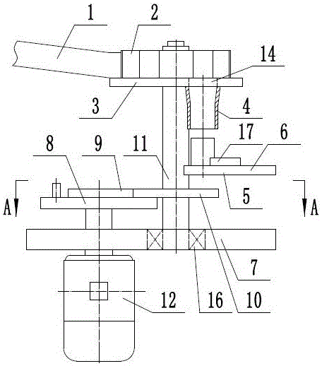
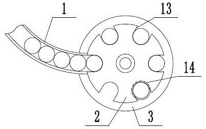
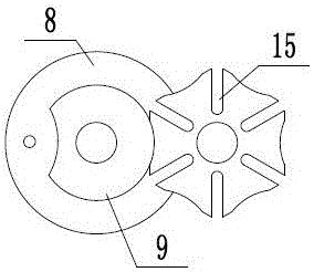
[0016] Such as figure 1 , figure 2 with image 3 As shown, a tank feeding device includes a feeding channel 1, a turntable 2, a support plate 3, a material guide tube 4, a station seat 5, a support shaft 6, a support base 7, a pin wheel 8, and a positioning plate 9 , sheave 10, drive shaft 11, drive motor 12, described support shaft 6 is rotatably arranged on support plate 3 and support base 7, and rolling bearing 16 is arranged between described support shaft 6 and support base 7, is conducive to support The shaft 6 rotates smoothly, which greatly reduces the wear between the supporting shaft 6 and the supporting base 7, and has good reliability. The support plate 3 is located above the support base 7 , the tur...


PUM


Abstract

The invention provides a tank feeding device and belongs to the technical field of metal tank machining. The tank feeding device comprises a feeding material way, a rotary plate, a material guide pipe, a station seat, a pin wheel, a positioning plate and a groove wheel. The rotary plate is coaxially installed at the upper end of a supporting shaft, and the lower end of the rotary plate is attached to a supporting plate. Six tank grooves are formed in the outer side of the rotary plate at equal intervals. The feeding material way is obliquely arranged on one side of the rotary plate and is in an arc shape. One end of the feeding material way is attached to the rotary plate. A feeding through hole is formed in the supporting plate. The material guide pipe is fixedly arranged at the lower end of the feeding through hole. The station seat is fixed below the material guide pipe. The groove wheel is coaxially installed on the supporting shaft. Six insertion grooves are formed in the groove wheel at equal intervals. The pin wheel is coaxially installed on a drive shaft and is further provided with the positioning plate. The positioning plate is attached to the groove wheel. A drive motor and the drive shaft are coaxially connected. By means of the tank feeding device, intermittent feeding of tanks is achieved, the structure is reasonable, cost is low, and in addition, deformation of the tanks in the feeding process is reduced.

Description

technical field [0001] The invention relates to the technical field of metal can body processing, in particular to a can body feeding device. Background technique [0002] The main products of cans are round, square and special-shaped cans, which can be subdivided into: food cans series, gift cans series, chemical cans series, etc. Common round cans are mainly chemical cans such as paint cans, spray cans, and paint cans. Common canning processes are: cutting the coil into rectangular sheets with a shear; painting and printing; cutting into strips; rolling into cylinders and welding side seams; repairing seams and coatings; flaring rolls Mouth; expanding cone; forming grooves or corrugations (also known as upper ribs); rolling back cover. In the automatic processing and assembly production line, the device that can automatically complete the supply and loading of the workpiece to the processing or assembly machine is called an automatic feeding device. In the process of wo...

Claims


Application Information

Patent Timeline
Patent Type & Authority Applications(China)
IPC IPC(8): B65G47/84
CPCB65G47/846B65G2201/0255
Inventor 赵锋朱辉夏忠
Owner ZHEJIANG ZHUOYI TEXTILE
Why Eureka
Try Eureka