
Micro powder conveying device

A conveying device and micro-powder technology, applied in conveyors, transportation and packaging, loading/unloading, etc., can solve problems such as endangering the health of workers

Inactive Publication Date: 2016-10-26
扬州锦盛微粉有限公司
View PDF0 Cites 1 Cited by
  • Summary
  • Abstract
  • Description
  • Claims
  • Application Information

AI Technical Summary

Problems solved by technology

[0004] The technical problem to be solved by the present invention is to provide a micropowder conveying device to solve the technical problem in the prior art that when the micropowder is transported manually to the semicolon machine, the flying micropowder forms dust and endangers the health of the staff

Method used


Image

  • Micro powder conveying device

Examples


Embodiment Construction

[0014] The present invention is described in further detail now in conjunction with accompanying drawing. These drawings are all simplified schematic diagrams, which only illustrate the basic structure of the present invention in a schematic manner, so they only show the configurations related to the present invention.

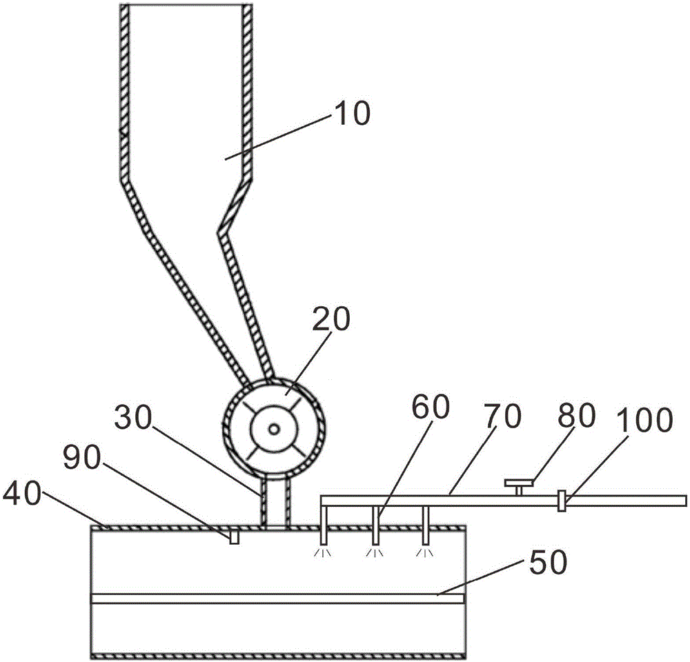
[0015] Such as figure 1 as shown, figure 1 It is a schematic structural diagram of a preferred embodiment of the micropowder conveying device of the present invention.

[0016] The present invention provides a micropowder conveying device, comprising a feed hopper 10, a solenoid valve 20, a feed pipe 30 and a conveying pipe 40, the solenoid valve 20 is connected to the feed hopper 10, and is used to control whether the feed hopper 10 conveys micropowder, The material pipeline 30 is connected under the electromagnetic valve 20, and the delivery pipeline 40 is horizontally installed under the feed pipeline 30. The inside of the delivery pipeline 40 is provided...


PUM


Abstract

The invention relates to a micropowder conveying device, which includes a feed hopper, a solenoid valve, a feed pipe and a conveying pipe. The conveying pipe is provided with a filter screen for filtering dust, and the filter screen is detachably installed on the side wall of the conveying pipe. , the top of the delivery pipeline is provided with an atomizing nozzle, a water supply pipeline and a control valve, one end of the water supply pipeline is connected to the atomization nozzle, the other end is connected to the water supply tank, and the control valve is set on the water supply pipeline to control the opening and closing of the water supply pipeline Closed, the control valve is connected with the solenoid valve at the same time, when the solenoid valve is opened, the control valve is triggered to open at the same time. The invention sprays atomized water vapor through the atomizing nozzle, so that the dust falls together with the water vapor to achieve the purpose of dust reduction. At the same time, the filter screen can filter out a part of the dust, so that the dust will not fly and float into the external environment, thereby avoiding dust. Harmful to the health of the staff, it can also avoid the waste of raw materials, reduce the labor intensity of workers, and ensure the normal operation of the conveying device.

Description

technical field [0001] The present invention relates to a conveying device, in particular, the present invention relates to a fine powder conveying device. Background technique [0002] In the industrial production of micropowder, it is necessary to classify and recycle the micropowder. Most of the existing technologies are classified by a semicolon machine. The micropowder enters the classification chamber of the semicolon machine, and the centrifugal force generated by the rotation of the rotor is used to separate the powder mixed in the gas-solid two-phase fluid according to the particle size for classification. Recycle. [0003] At present, the method of manual handling and filling is usually used to send the micropowder into the semicolon machine. The labor intensity of the staff is relatively high, and the work efficiency is low, which increases the operating cost of the enterprise. At the same time, during the process of handling and filling, dust will be generated ...

Claims


Application Information

Patent Timeline
IPC IPC(8): B65G69/18B65G65/40B65G65/00
CPCB65G69/188B65G65/005B65G65/40B65G2201/04B65G2203/02B65G2203/042
Inventor 朱宏生
Owner 扬州锦盛微粉有限公司
Learn More