Motor Cooling Device and Cooling and Lubricating System of Power Coupling Mechanism

A power coupling and motor cooling technology, which is applied in the direction of electromechanical devices, cooling/ventilation devices, transmission parts, etc., can solve the problems of low utilization rate of cooling oil, large space occupied by motors, complex shell structure, etc., and improve output utilization rate , the effect of improving accuracy

Active Publication Date: 2020-09-01
GUANGZHOU AUTOMOBILE GROUP CO LTD
View PDF6 Cites 0 Cited by
  • Summary
  • Abstract
  • Description
  • Claims
  • Application Information

AI Technical Summary

Problems solved by technology

[0002] In the existing transmission or coupling device motor cooling system, the cooling water circuit is directly processed on the motor casing, and the cooling of the motor is realized through the circulation of cooling water in the cooling water circuit. However, the structure of the motor casing in this scheme is relatively complex, the processing of the shell is difficult, and the motor occupies a large space; therefore, it is more feasible to cool the motor by installing a cooling oil pipe outside the motor; however, due to the relatively small space of the transmission or power coupling mechanism, As a result, it is difficult to arrange the oil circuit of the cooling oil pipe. Generally, the cooling oil pipes are arranged in parallel above or on the side of the motor, resulting in poor cooling effect of the motor. The utilization rate of the cooling oil output in the cooling oil pipe is low, resulting in cooling oil The output is wasted; in addition, this arrangement of cooling oil pipes is not suitable for cooling multiple motors separately, and there are disadvantages in the application

Method used


Image

  • Motor Cooling Device and Cooling and Lubricating System of Power Coupling Mechanism
  • Motor Cooling Device and Cooling and Lubricating System of Power Coupling Mechanism

Examples


Embodiment Construction

[0019] The specific implementation manners of the present invention will be further described in detail below in conjunction with the accompanying drawings and embodiments. The following examples are used to illustrate the present invention, but are not intended to limit the scope of the present invention.

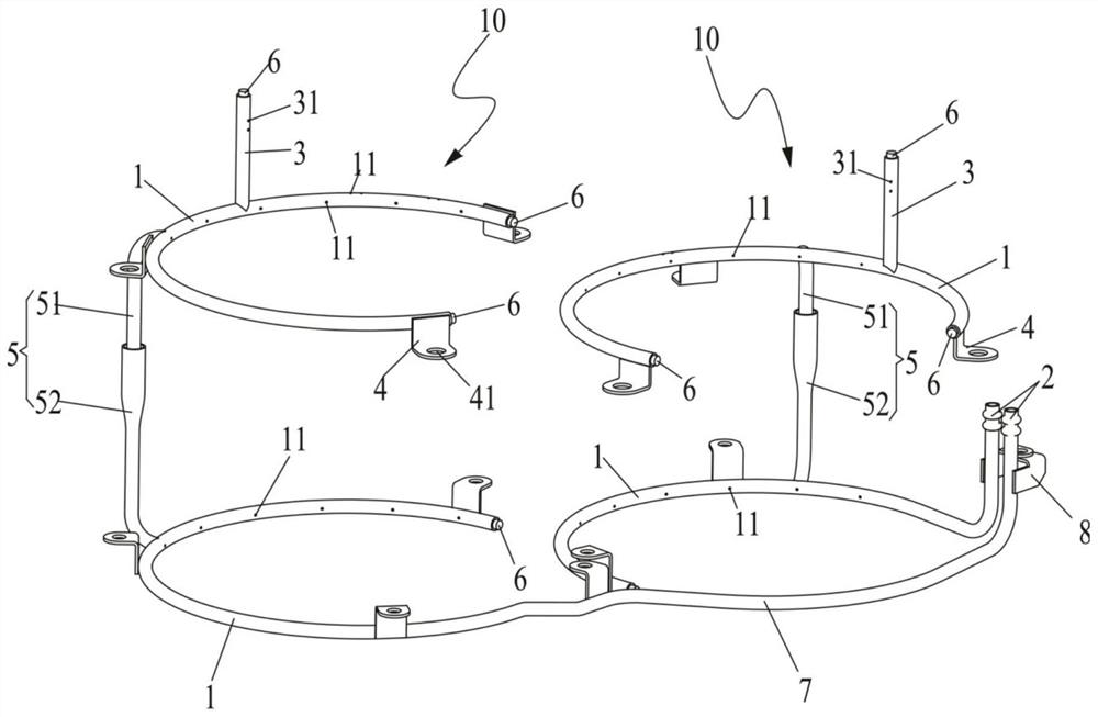
[0020] like figure 1 As shown, the motor cooling device of the power coupling mechanism of the embodiment of the present invention includes at least one liquid spray pipe assembly 10 for spraying coolant to cool the motor, and each liquid spray pipe assembly 10 includes at least two surrounding motor outer contours The liquid spray ring pipe 1 provided, each liquid spray pipe assembly 10 is provided with an independent liquid infusion end 2, and the liquid spray ring pipe 1 of the liquid spray pipe assembly 10 is not communicated with the liquid spray ring pipe 1 of other liquid spray pipe assemblies 10 , that is, the cooling liquid in each liquid spray pipe assembly 10 i...


PUM


Abstract

The invention relates to the field of automobiles and discloses a motor cooling device and a cooling lubricating system of a power coupling system. The motor cooling device comprises at least one liquid injection pipe assembly which is used for injecting cooling liquid to cool a motor. Each liquid injection pipe assembly comprises at least two annular liquid injection pipes which are arranged around the outer contour of the motor and communicate with each another. The annular liquid injection pipes of each liquid injection pipe assembly do not communicate with the annular liquid injection pipes of the other liquid injection pipe assemblies. Multiple first liquid injection nozzles are arranged on the side, close to the motor, of each annular liquid injection pipe around the annular wall. Each liquid injection pipe assembly is provided with a liquid conveying end, wherein the cooling liquid flows into each annular liquid injection pipe in the corresponding liquid injection pipe assembly through the liquid conveying end. According to the motor cooling device and the cooling lubricating system of the power coupling mechanism, the annular liquid injection pipes of the liquid injection pipe assemblies are arranged around a shell of the motor, the multiple first liquid injection nozzles are arranged on the inner side walls, close to the shell of the motor, of the annular liquid injection pipes, and due to the fact that the annular liquid injection pipes are arranged around the shell of the motor, the cooling liquid can be evenly scattered to the whole shell of the motor after being injected out through the first liquid injection nozzles, and the output utilization rate of the cooling liquid is increased.

Description

technical field [0001] The invention relates to the field of automobiles, in particular to a motor cooling device and a cooling lubricating system of a power coupling mechanism. Background technique [0002] In the existing transmission or coupling device motor cooling system, the cooling water circuit is directly processed on the motor casing, and the cooling of the motor is realized through the circulation of cooling water in the cooling water circuit. However, the structure of the motor casing in this scheme is relatively complex, the processing of the shell is difficult, and the motor occupies a large space; therefore, it is more feasible to cool the motor by installing a cooling oil pipe outside the motor; however, due to the relatively small space of the transmission or power coupling mechanism, As a result, it is difficult to arrange the oil circuit of the cooling oil pipe. Generally, the cooling oil pipes are arranged in parallel above or on the side of the motor, re...

Claims


Application Information

Patent Timeline
Patent Type & Authority Patents(China)
IPC IPC(8): F16H57/04H02K9/19
CPCF16H57/042F16H2700/00H02K9/19
Inventor 张雄赵江灵黄少堂梅骜吴为理李千红
Owner GUANGZHOU AUTOMOBILE GROUP CO LTD
Why Eureka
Try Eureka