Caulking fixation type power element and expansion valve using the same

A technology of power components and riveting, which is applied in the field of expansion valves, can solve problems such as the protruding and exposed opening of the connecting part 3, the damage durability of the diaphragm 2, and the lowering of the diaphragm 2, so as to simplify the positioning action, suppress deformation, and prevent damage. Effect

Inactive Publication Date: 2016-10-26
FUJIKOKI MFG CO LTD
View PDF9 Cites 5 Cited by
  • Summary
  • Abstract
  • Description
  • Claims
  • Application Information

AI Technical Summary

Problems solved by technology

In addition, the diaphragm 2 may protrude from the opening of the receiving member 3 and be exposed due to internal pressure.
[0024] In such a case, when only the riveting-fixed power element in which the working gas is enclosed is manufactured and transported in another process, the diaphragm 2 may come into contact with the inner wall of the storage box for transportation, other power elements, etc., and the diaphragm 2 may be damaged. There is a concern that its durability will decrease or the diaphragm 2 will be damaged.

Method used


Image

  • Caulking fixation type power element and expansion valve using the same
  • Caulking fixation type power element and expansion valve using the same
  • Caulking fixation type power element and expansion valve using the same

Examples


Embodiment Construction

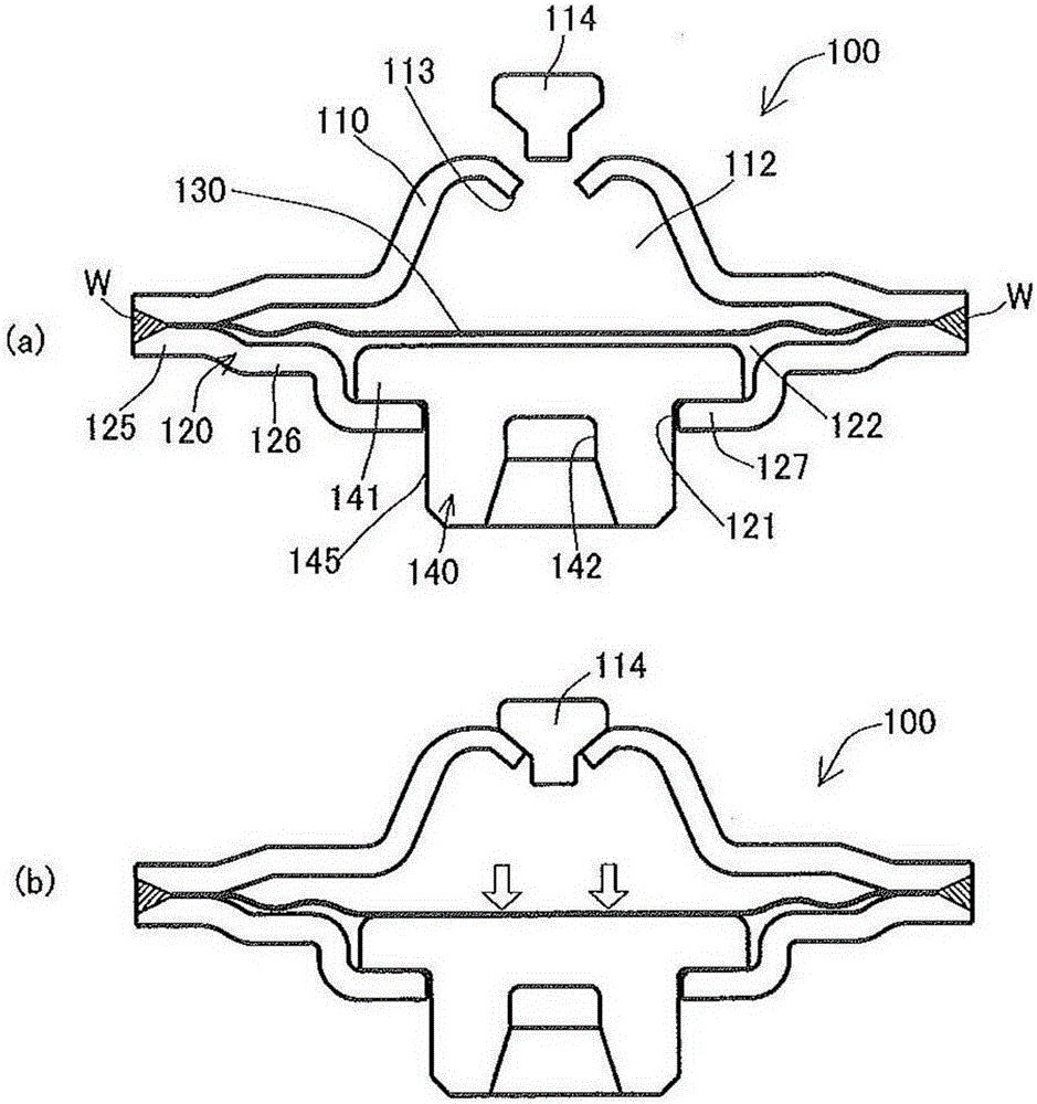
[0068] figure 1 It is a longitudinal sectional view showing the structure of an embodiment of the riveted power element of the present invention, figure 1 (a) represents the state before the working gas is sealed, figure 1 (b) shows the state after the working gas is sealed.

[0069] Such as figure 1 As shown in (a), the riveted fixed power element 100 is composed of an upper cover member 110, a receiving member 120 having a through hole 121 in the center, a diaphragm 130 sandwiched between the upper cover member 110 and the receiving member 120, and a receiving member 120 from the receiving member 120. The through hole 121 of the stop member 140 is formed.

[0070] A pressure chamber 112 is formed inside between the upper cover member 110 and the diaphragm 130 . In addition, a working gas such as an inert gas is sealed in the pressure working chamber 112 .

[0071] Here, a sealing hole 113 for sealing the above-mentioned working gas is formed in the central part of t...


PUM


Abstract

A caulking fixation type power element has a diaphragm, an upper lid member forming a pressure actuation chamber with a working gas, a receiving member provided with a through hole in its center portion and arranged in an opposite side to the upper lid member in relation to the diaphragm, and a stopper member arranged in a lower space formed between the diaphragm and the receiving member, and is integrated according to a circumferential welding by lapping the upper lid member, the diaphragm and the receiving member, the stopper member has a main body portion inserted to the through hole of the receiving member, and a flange portion having a larger diameter than the through hole and formed in one end of the main body portion, and the flange portion is arranged so as to come into contact with the receiving member from the lower space side.

Description

technical field [0001] The present invention relates to an expansion valve with a built-in temperature sensing mechanism used in a refrigeration cycle, and more particularly to an expansion valve in which a power element is attached to a valve main body by a riveting structure. Background technique [0002] Conventionally, in the refrigeration cycle mounted on an automobile air conditioner, etc., in order to omit installation space and piping work, a temperature expansion valve with a built-in temperature sensing mechanism that adjusts the passage amount of the refrigerant according to the temperature is used (for example, refer to Patent Document 1 ). The valve body of such an expansion valve has an inlet port through which high-pressure refrigerant is introduced, and a valve chamber communicating with the inlet port. [0003] The spherical valve member arranged in the valve chamber faces the valve seat of the valve hole opened in the valve chamber, and the opening degree ...

Claims


Application Information

Patent Timeline
Patent Type & Authority Applications(China)
IPC IPC(8): F16K31/126F16K27/08F25B41/06
CPCF16K27/08F16K31/126F25B2341/06F25B41/335F25B2341/0683F25B2500/01F16K31/002F25B49/02
Inventor 松田亮早川润哉
Owner FUJIKOKI MFG CO LTD
Why Eureka
Try Eureka