Movable camera device for intelligent transportation

A camera device and intelligent transportation technology, applied in the direction of image communication, color TV parts, TV system parts, etc., can solve the problems of unsatisfactory camera monitoring effect and inconvenient adjustment, so as to reduce the probability of camera damage, Extended service life, better camera effect

Inactive Publication Date: 2016-10-26
成都捷科菲友信息技术有限公司
View PDF8 Cites 9 Cited by
  • Summary
  • Abstract
  • Description
  • Claims
  • Application Information

AI Technical Summary

Problems solved by technology

[0004] The purpose of the present invention is to solve the technical problem of the unsatisfactory monitoring effect of the camera on the existing road and the technical problem of inconvenient adjustment. The present invention provides a movable camera device for intelligent traffic

Method used


Image

  • Movable camera device for intelligent transportation
  • Movable camera device for intelligent transportation

Examples


Embodiment 1

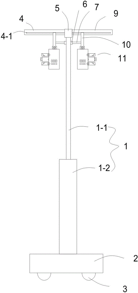
[0017] Such as Figures 1 to 2 As shown, the present embodiment provides a mobile camera device for intelligent traffic, including a light pole 1, which is characterized in that the light pole 1 includes a support base 1-2 at the bottom and a vertical support set on the support base 1-2. Straight bar 1-1, support seat 1-2 is provided with movable seat 2, and mobile seat 2 is provided with mobile roller 3, and vertical bar 1-1 top is provided with fixed block 5, and fixed block 5 left and right ends are welded respectively The left crossbar 4 and the right crossbar 9, the left crossbar 4 and the right crossbar 9 are located on the same horizontal line, and the left crossbar 4 and the right crossbar 9 are horizontally provided with bar-shaped card slots 4-1 at the same height. A camera fixing device 10 capable of reciprocating movement along the respective strip-shaped card slots 4-1 is snapped inside the two strip-shaped card slots 4-1. The left and right sides of the upper en...

Embodiment 2

[0019] Such as Figures 1 to 2 As shown, the present embodiment provides a mobile camera device for intelligent traffic, including a light pole 1, which is characterized in that the light pole 1 includes a support base 1-2 at the bottom and a vertical support set on the support base 1-2. Straight bar 1-1, support seat 1-2 is provided with movable seat 2, and mobile seat 2 is provided with mobile roller 3, and vertical bar 1-1 top is provided with fixed block 5, and fixed block 5 left and right ends are welded respectively The left crossbar 4 and the right crossbar 9, the left crossbar 4 and the right crossbar 9 are located on the same horizontal line, and the left crossbar 4 and the right crossbar 9 are horizontally provided with bar-shaped card slots 4-1 at the same height. A camera fixing device 10 capable of reciprocating movement along the respective strip-shaped card slots 4-1 is snapped inside the two strip-shaped card slots 4-1. The left and right sides of the upper en...


PUM


Abstract

The invention discloses a movable camera device for intelligent transportation, and relates to the technical field of camera devices. The movable camera device for intelligent transportation comprises a lamp rod; the lamp rod includes a support base at the bottom, and a vertical rod arranged on the support base; a moving base is arranged below the support base; a moving roller is arranged under the moving base; a fixed block is arranged at the top end of the vertical rod; a left cross bar and a right cross bar are respectively welded at the left and right two ends of the fixed block; strip-shaped clamping grooves are transversely formed in the same heights of the left cross bar and the right cross bar; camera fixing devices capable of performing a reciprocating motion in respective strip-shaped clamping grooves are clamped in the two strip-shaped clamping grooves; combined cameras are hinged to the lower ends of the camera fixing devices, and include shells; and infrared cameras A, high-definition cameras and infrared cameras B are arranged on one sides of the shells from top to bottom in sequence. The movable camera device for intelligent transportation has the advantages of simple structure, convenience for monitoring the night conditions in multiple angles and high practicability.

Description

technical field [0001] The present invention relates to the technical field of camera devices, and more particularly relates to a movable camera device for intelligent transportation. Background technique [0002] With the advancement of science and technology, urban construction promotes high-tech intelligence. Nor are road safety concerns limited to the inconveniences of poor lighting. For example, when there is a traffic accident or public security problem in a certain location, it is necessary to obtain surveillance images of a specific location. Due to the small number of monitoring equipment in the current urban construction and the large number of dead spots in the observation area, this requirement cannot be realized. [0003] At present, the cameras on the market are all used around a single high-definition lens with dot matrix infrared, which is convenient for 24-hour monitoring during the day and night. Although this type of camera works well, once the camera is ...

Claims


Application Information

Patent Timeline
Patent Type & Authority Applications(China)
IPC IPC(8): F16M11/42F16M11/28F16M11/04H04N5/225
CPCF16M11/048F16M11/28F16M11/42H04N23/51
Inventor 程飞
Owner 成都捷科菲友信息技术有限公司
Why Eureka
Try Eureka