Bearing seat and drying machine using same

A technology for bearing housings and dryers, applied to the rigid support of bearing components, bearing elements, shafts and bearings, etc., can solve the problems of difficult oil filling of bearing end covers, low oil filling efficiency, etc. The effect of work efficiency

Inactive Publication Date: 2016-10-26
CHINA TOBACCO HENAN IND
View PDF6 Cites 4 Cited by
  • Summary
  • Abstract
  • Description
  • Claims
  • Application Information

AI Technical Summary

Problems solved by technology

[0004] The purpose of the present invention is to provide a bearing seat, which is used to solve the above-mentioned problems of difficult oil injection at the end cover of the bearing and low oil injection efficiency; the purpose of the present invention is also to provide a dryer using the bearing seat to meet Lubrication requirements in dryer transmission to ensure work efficiency

Method used


Image

  • Bearing seat and drying machine using same
  • Bearing seat and drying machine using same

Examples


Embodiment Construction

[0022] Embodiments of the present invention will be further described below in conjunction with the accompanying drawings.

[0023] A specific embodiment of a dryer with a bearing housing of a self-lubricating device of the present invention.

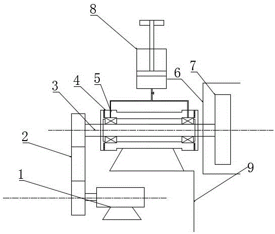
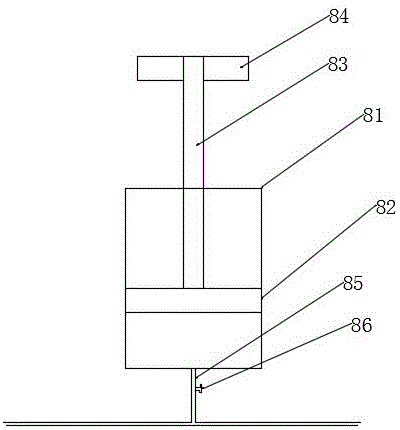
[0024] In this embodiment, a dryer with a self-lubricating bearing housing includes a fan, a fluidized drying chamber, a vibrating device, and a driving device. Such as figure 1 , the bearing seat 4 is equipped on a fan, and the fan is used as a part of the vibrating fluidized dryer to supply high-temperature gas to the drying chamber. The bearing seat 4 is installed on the frame 9, and the self-lubricating device 8 is installed on the bearing seat shell. One end of the transmission shaft 3 installed in the bearing seat 4 is connected with the rotating shaft belt of the motor 1 through the belt 2, and the other end passes through the impeller for protection. The cover 6 is connected with the fan impeller 7, and the motor transmits pow...


PUM


Abstract

The invention provides a bearing seat and a drying machine using the same. The bearing seat is provided with a self-service lubrication device which is relatively fixedly arranged with a shell, wherein the self-service lubrication device comprises an oil storage cavity; a piston and a press rod used for driving the piston to move downwards are arranged in the oil storage cavity; the self-service lubrication device further comprises an oil transmission tube communicating with the oil storage cavity; and the oil transmission tube communicates with an oil nozzle in the bearing seat. The problem of influence on the working efficiency due to difficult oil injection for lubrication for the bearing seat of a fan on the drying machine is solved.

Description

technical field [0001] The invention relates to a bearing housing with a self-lubricating device and a dryer using the bearing housing. Background technique [0002] The vibrating fluidized dryer is one of the special equipment for drying tobacco stems. It has the characteristics of simple structure and high drying efficiency. The equipment has three drying areas, and the fans in the three areas output high-temperature hot air, so that the temperatures in the three drying areas are all above 100°C. During preheating and daily production, due to the high temperature of the working environment, the bearing of the fan drive shaft is easy to heat and damage, and the transmission part of the equipment needs to be lubricated regularly. [0003] The fan transmission shaft is installed on the bearing seat, one end of the transmission shaft is connected with the motor, and the other end is connected with the fan impeller. The motor transmits power to the drive shaft through the bel...

Claims


Application Information

Patent Timeline
Patent Type & Authority Applications(China)
IPC IPC(8): F16N3/06F16N21/00F16N23/00F16C35/00
CPCF16N3/06F16C35/00F16N21/00F16N23/00F16N2210/14F16N2280/00
Inventor 冀跃峰卢昂冯银龙张世强刘彦敏刘前进朱磊范丽红赵明辉
Owner CHINA TOBACCO HENAN IND
Why Eureka
Try Eureka