
Negative ion LED illuminating device

A technology for negative ion generation and lighting devices, which is applied in lighting devices, lighting devices, fixed lighting devices, etc., can solve the problems of affecting the release amount, release speed restriction, and not saving energy, and achieves increased negative ion release, high lighting intensity and luminosity , The effect of improving the bactericidal effect

Active Publication Date: 2016-10-26
徐廷明
View PDF9 Cites 3 Cited by
  • Summary
  • Abstract
  • Description
  • Claims
  • Application Information

AI Technical Summary

Problems solved by technology

[0007] Third: Existing products have a small negative ion release coverage and slow release speed, which seriously affects the release amount. Therefore, the existing products have severely restricted negative ions in terms of product design difficulty, their own structure, and release speed. The amount of negative ions released by the device;
[0008] At the same time, in the research and design, it is often found that there are many technical problems in this existing product structure;
[0009] Fourth: During the design and research process, it was found that the generation and release of negative ions can be achieved by using a smaller micro-current through a specific technology, but if the current is too low, it may lead to weak light intensity, affect the normal lighting work of the lamp, and not save energy;
[0010] Fifth: During the design and research process, it was found that the heat dissipation performance of the lamp will be affected after the structural design such as negative ion generator is adopted, especially the traditional lampshade has poor heat dissipation;
[0011] Sixth, the stability and reliability of the product are poor, and the technology of the automatic control performance of the lighting device is relatively backward.

Method used


Image

  • Negative ion LED illuminating device
  • Negative ion LED illuminating device
  • Negative ion LED illuminating device

Examples


Embodiment Construction

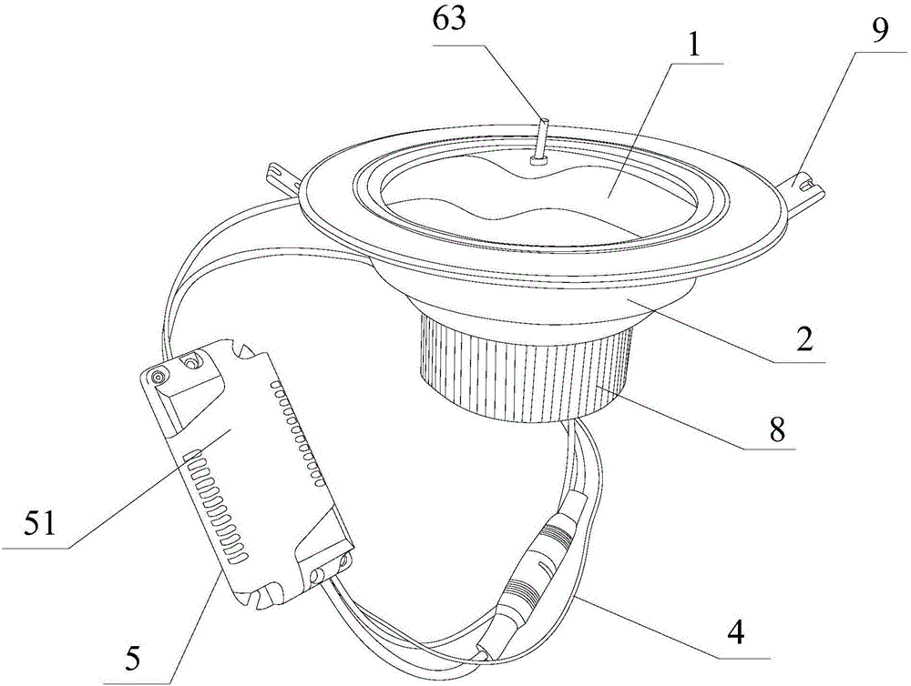
[0063] The technical solutions of the present invention will be clearly and completely described below in conjunction with the accompanying drawings. Apparently, the described embodiments are some of the embodiments of the present invention, but not all of them. Based on the embodiments of the present invention, all other embodiments obtained by persons of ordinary skill in the art without making creative efforts belong to the protection scope of the present invention.

[0064] In the description of the present invention, it should be noted that unless otherwise specified and limited, the terms "installation", "connection" and "connection" should be understood in a broad sense, for example, it can be a fixed connection or a detachable connection. Connected, or integrally connected; it can be mechanically connected or electrically connected; it can be directly connected or indirectly connected through an intermediary, and it can be the internal communication of two components. ...


PUM


Abstract

The invention discloses a negative ion LED illuminating device. The negative ion LED illuminating device comprises a lamp shade, a rear casing, an illuminating lamp component, connecting leads, an electric control device, a first negative ion generation device, a second negative ion generation device and the like. The negative ion LED illuminating device provided by the invention has technical improvements on multiple aspects; and multiple creative technical schemes and structures are designed, and the technical improvements on the multiple aspects are obtained at the same time, so that good market prospect and economic benefits are surely brought.

Description

technical field [0001] The invention relates to the technical field of negative ion equipment, in particular to a negative ion LED generating lighting device. Background technique [0002] In daily life, due to the increasingly serious destruction of the ecological environment in modern society, weather phenomena such as haze, light fog, blowing sand, floating dust, and sandstorms have become more frequent, and the content of floating dust in the air has increased, resulting in poorer air quality. . [0003] There are a great variety of anion generators in the existing market, which are usually installed indoors to purify the air in the room. At the same time, some lighting lamps will be installed in the general room to play the role of indoor lighting; [0004] But, the product that the anion generator of the simple design structure that occurs in the prior art combines with the lighting lamp; There are various technical problems in this existing product structure; [00...

Claims


Application Information

Patent Timeline
IPC IPC(8): F21S8/04F21V33/00F21V23/00F21V23/04F21V3/02F21V3/04F21V29/87F21V29/77F21V29/89F21V21/02H01T23/00C09D163/00C09D201/00C09D7/12C09D5/33F21Y115/10
CPCC09D5/004C09D7/61C09D163/00F21S8/04F21V3/02F21V3/061F21V3/10F21V21/02F21V23/003F21V23/0464F21V23/0471F21V29/77F21V29/87F21V29/89F21V33/00H01T23/00C08L101/14C08K13/02C08K3/34C08K2003/221
Inventor 徐廷明
Owner 徐廷明
Learn More