Light collecting system

A technology of light collection and collector, applied in the field of light collection system, can solve problems such as limiting energy coupling efficiency, increasing system cost, reducing reflector reflectivity, etc., to ensure lighting brightness, ensure lighting effect, and alleviate brightness differences Effect

Active Publication Date: 2016-10-26
悦来湖(山东)数字经济产业园运营管理有限公司
View PDF6 Cites 4 Cited by
  • Summary
  • Abstract
  • Description
  • Claims
  • Application Information

AI Technical Summary

Problems solved by technology

Although the cost of the Fresnel lens is relatively low, due to the limitation of its principle and the small core diameter of the optical fiber, the coupling efficiency of sunlight converging into the optical fiber is low, and most of the light energy is lost at the end face of the optical fiber; Large-diameter plastic optical fiber is an effective way to improve its light energy coupling efficiency, but the invisible light such as ultraviolet and infrared, which accounts for about half of the total energy of sunlight, is converged by the lens, and the temperature at the point of convergence suddenly rises to hundreds of degrees, which is enough to burn Plastic optical fiber makes the optical fiber solar lighting system unable to use low-cost, large-core plastic optical fiber, and can only use high-cost, small-core-diameter quartz optical fiber, which increases the system cost and limits its energy coupling efficiency. Impossible for tunnel lighting
[0006] In order to solve the problem of energy coupling efficiency of optical fiber solar lighting, a tunnel sunlight secondary reflection lighting system has been proposed, such as figure 2 As shown, the system includes a first reflector 201 and a second reflector 202, the second reflector 202 is mounted on the top of the tunnel entrance, the first reflector 201 reflects sunlight into the second reflector Mirror 202, through the secondary reflection of the second reflecting mirror 202, enters the entrance of the tunnel. Therefore, the system solves the problem of low coupling efficiency between the lens and light, and saves expensive transmission light. However, as figure 2 The system requires two reflectors to be used together, which increases the difficulty of installation, and the light energy utilization rate is too low after the sunlight is reflected twice. At the same time, because the first reflector 201 is installed horizontally, dust, rain, etc. It is easy to accumulate on the reflector, which greatly reduces the reflectivity of the reflector, which intensifies the loss of light energy

Method used


Image

  • Light collecting system
  • Light collecting system
  • Light collecting system

Examples


Embodiment Construction

[0025] The technical solutions in the embodiments of the present invention will be clearly and completely described below in conjunction with the accompanying drawings in the embodiments of the present invention. Obviously, the described embodiments are only some, not all, embodiments of the present invention. Based on the embodiments of the present invention, all other embodiments obtained by persons of ordinary skill in the art without making creative efforts belong to the protection scope of the present invention.

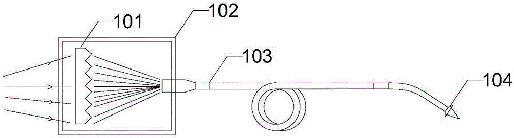
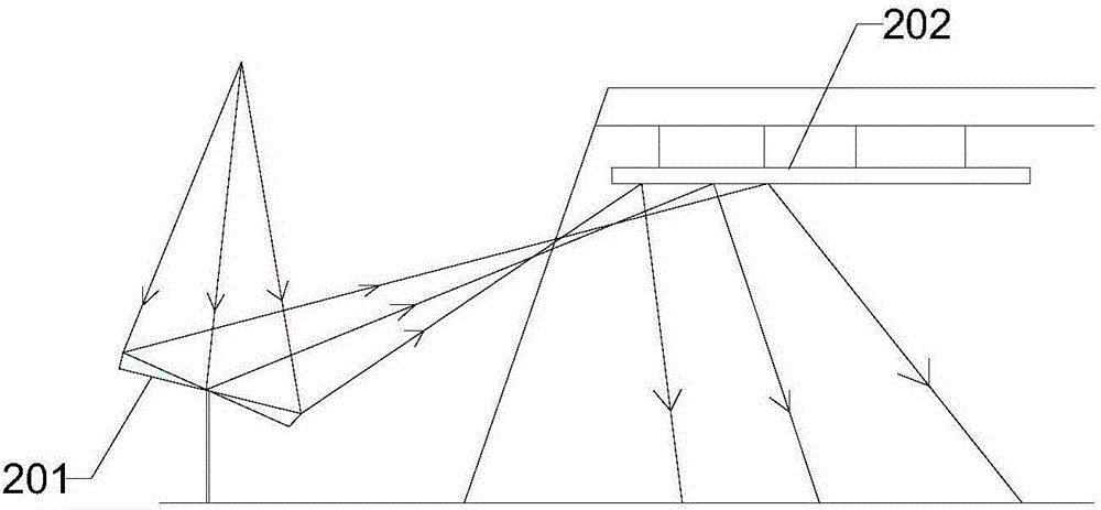
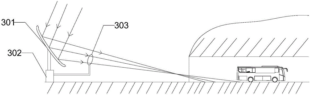
[0026] to overcome figure 1 with figure 2 In order to effectively reduce the cost of the existing system for improving the brightness of the tunnel entrance and effectively improve the light energy utilization rate of the existing light collection system, an embodiment of the present invention provides a tunnel entrance lighting system, such as image 3 As shown, the tunnel entrance lighting system includes such as Figure 4 The light collecting system shown,...


PUM


Abstract

The invention discloses a light collecting system and belongs to the field of electromechanical systems of the road and bridge field. The light collecting system is used for illuminating a tunnel entrance section and comprises a reflection mirror, a mechanical platform and a controller, wherein the reflection mirror is arranged on the mechanical platform and is used for reflecting sunlight into the tunnel entrance and enabling the reflective light rays to uniformly scatter on the ground of the whole entrance section; the controller is used for sending a control command to the mechanical platform; the mechanical platform controls the reflection mirror to move according to the control command so as to enable the light reflected by the reflection mirror to go into the tunnel entrance. The invention aims to provide the light collecting system, so that the sunlight is effectively utilized to realize natural illumination of the tunnel entrance section, the illumination cost and energy consumption of the tunnel entrance section are reduced, and the efficiency for solar energy utilization of the existing light collecting system is improved.

Description

technical field [0001] The present invention relates to the field of optical elements, systems or instruments, in particular to a light collection system. Background technique [0002] Since the entrance section of the tunnel is the junction of the closed dark space inside the tunnel and the bright space outside, due to the huge brightness difference inside and outside the tunnel, the driver will have a huge visual light and dark mutation when entering the tunnel, forming a "black hole effect" when entering the tunnel during the day and night " and the "white hole effect" can easily lead to driving safety accidents. Therefore, the lighting at the entrance section of the highway tunnel is extremely important, and the illuminance index of the lighting is extremely strict. It must not only consider factors such as the structural size of the tunnel, the design speed of the vehicle, but also meet very special standards for spatial light field distribution, and must match the brig...

Claims


Application Information

Patent Timeline
Patent Type & Authority Applications(China)
IPC IPC(8): F21S11/00F21V23/00F21V14/04F21V7/04F21W131/101
CPCF21S11/005F21V7/04F21V14/04F21V23/003F21W2131/101
Inventor 陈伟民周园会史玲娜刘显明雷小华
Owner 悦来湖(山东)数字经济产业园运营管理有限公司
Why Eureka
Try Eureka