Optical efficiency testing device and optical efficiency testing method for infrared fiber image-transmitting bundle

A technology of optical efficiency and testing device, applied in testing optical fiber/optical waveguide equipment, testing optical performance, etc., can solve the problems of inability to test, and the optical fiber image beam cannot use parallel beams, etc., to achieve intuitive results

Active Publication Date: 2016-10-26
XI'AN INST OF OPTICS & FINE MECHANICS - CHINESE ACAD OF SCI
View PDF4 Cites 9 Cited by
  • Summary
  • Abstract
  • Description
  • Claims
  • Application Information

AI Technical Summary

Problems solved by technology

Therefore, parallel beams cannot be used when measuring the transmittance of optical fiber image beams
However, compared with visible light optical fiber image transmission bundles, the optical efficiency of infrared optical fiber image transmission bundles has a great relationship with its materials

Method used


Image

  • Optical efficiency testing device and optical efficiency testing method for infrared fiber image-transmitting bundle
  • Optical efficiency testing device and optical efficiency testing method for infrared fiber image-transmitting bundle
  • Optical efficiency testing device and optical efficiency testing method for infrared fiber image-transmitting bundle

Examples


Embodiment Construction

[0044] The present invention will be further described below in conjunction with the accompanying drawings.

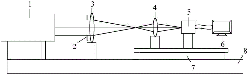
[0045] Such as figure 1 As shown, it is a schematic diagram of the device in Step 1 of the present invention, including a standard black body 1, a front imaging objective lens 3, a subsequent coupling lens group 4, an infrared detector 5 and an image acquisition computer 6, and the specific test method is as follows:

[0046] Step 1: Set the standard blackbody 1 to a fixed temperature (to avoid saturation of the detector response) and keep it constant. Place the standard blackbody 1 at a distance of 30 times the focal length of the front imaging objective lens to approximate the incidence of parallel light to ensure that the standard blackbody 1 passes through the front Set the imaging objective lens 3 into a clear image; place the adjustable diaphragm 2 before the front imaging objective lens 3, for changing the numerical aperture of the front imaging objective lens 3...


PUM


Abstract

The invention provides an optical efficiency testing method for an infrared fiber image-transmitting bundle, wherein the optical efficiency of the to-be-tested fiber image bundle is tested through stable infrared radiation energy I1 which is obtained by a standard black body and infrared radiation energy that is output through transmission of the fiber image-transmitting bundle. Compared with a method of testing optical fiber damping (unit dB/m) or parallel light transmittance through a truncation method in current fiber testing, the optical efficiency testing method has advantages of higher visuality and higher pertinency. The optical efficiency testing method more accords with optical transmission characteristic of the fiber and can more accurately reflect optical transmission performance of the fiber image-transmitting bundle. The optical efficiency testing method can settle a problem of no specialized instrument and device for testing the performance of the infrared fiber image-transmitting bundle. Furthermore an optical efficiency testing device of the optical efficiency testing method can be used for testing other main indexes such as arrangement irregularity and fiber breakage rate in the fiber image-transmitting bundle.

Description

technical field [0001] The invention relates to the field of optical fiber performance testing, in particular to an optical efficiency testing method of an infrared optical fiber image transmission bundle. Background technique [0002] It has become a new type of optical imaging system to use the passive optical fiber image transmission beam as the image transmission element to realize the transmission and transformation of light energy in the two-dimensional distribution of space, so as to achieve the purpose of specific photoelectric detection. Among them, the optical fiber image transmission bundle is an integrated optical device composed of a large number of optical fibers arranged according to certain rules, which has the characteristics of light weight, good flexibility, and large degree of freedom. In addition, compared with traditional imaging devices such as CCD and CMOS, the optical fiber image transmission bundle can transmit images passively and in real time, can...

Claims


Application Information

Patent Timeline
IPC IPC(8): G01M11/02
CPCG01M11/33
Inventor 闫兴涛李福马小龙贺应红吕娟赵意意杨建峰
Owner XI'AN INST OF OPTICS & FINE MECHANICS - CHINESE ACAD OF SCI
Why Eureka
Try Eureka